


B2
-
19
IM 34M06H62-02E
2nd Edition : June 2008-00
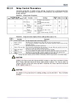
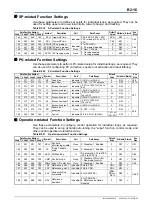
Table B2.24 PID Parameters (3/4)
Data Position Number
Symbol Description Unit
Data
Range Default
Value
Attribute
Stored
See
Also
Loop 1 Loop 2 Loop 3 Loop 4
241 441 641 841 3.SP Set
point
Industrial
PRL to PRH
PRL
RW
Irregular
B2.4
C4.1
242 442 642 842 3.A1
Alarm 1 preset value
Industrial -30000 to 30000
PRH RW
C8
243 443 643 843 3.A2
Alarm 2 preset value
PRL RW
244 444 644 844 3.A3
Alarm 3 preset value
PRH RW
245 445 645 845 3.A4
Alarm 4 preset value
PRL RW
246 446 646 846 3.PB
Proportional band
%
1 to 9999 (0.1 to 999.9%)
50 RW
C6.2
247 447 647 847 3.TI
Integral time
Second 0: OFF, 1 to 6000 (1 to 6000 s)
240 RW
C6.3
248 448 648 848 3.TD
Derivative time
Second 0: OFF, 1 to 6000 (1 to 6000 s)
60 RW
C6.4
249 449 649 849 3.OH
Upper output limit
%
-5.0 to 105.0% if OL < OH
Fixed at OL if OL
OH
1000 RW
C2.4.2
250 450 650 850 3.OL Lower
output
limit
0 (1000 in heating/
cooling control)
RW
251 451 651 851 3.MR Manual
reset
value
%
-5.0 to 105.0%
500 RW
C6.3
252 452 652 852 3.HYS
ON/OFF control
hysteresis
Industrial 0 to (PRH - PRL)
(PRH - PRL) x 0.5%
RW
C2.4.1
253 453 653 853 3.DR
Forward/
reverse switch
None
0: Reverse, 1: Forward
(Fixed at 0 in heating/cooling
control)
0 RW
C6.1
254 454 654 854 3.GAIN.C
Cooling
gain
%
1 to 999 (1 to 999%)
100 RW
C2.4.3
255 455 655 855 3.HYS.C
Cooling ON/OFF control
hysteresis
Industrial 0 to (PRH - PRL)
(PRH - PRL) x 0.5%
RW
C2.4.4
256 456 656 856 3.DB Dead
band
Industrial
PID control:
-10.0 to 10.0% of (PRH - PRL)
ON/OFF control:
-50.0 to 50.0% of (PRH - PRL)
0 RW
C2.4.3
C2.4.4
257 457 657 857 3.POUT
Preset
output
%
-50 to 1050 (-5.0 to 105.0%)
0 RW
C7.1
258 458 658 858 3.POUT.C
Cooling
preset
output
%
-50 to 1050 (-5.0 to 105.0%)
0 RW
Irregular: You need to execute a specific procedure every time to update stored set point values.
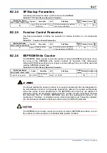
Table B2.24 PID Parameters (4/4)
Data Position Number
Symbol Description Unit
Data
Range Default
Value
Attribute
Stored
See
Also
Loop1 Loop2 Loop3 Loop4
261 461 661 861 4.SP Set
point
Industrial
PRL to PRH
PRL
RW
Irregular
B2.4
C4.1
262 462 662 862 4.A1
Alarm 1 preset value
Industrial -30000 to 30000
PRH RW
C8
263 463 663 863 4.A2
Alarm 2 preset value
PRL RW
264 464 664 864 4.A3
Alarm 3 preset value
PRH RW
265 465 665 865 4.A4
Alarm 4 preset value
PRL RW
266 466 666 866 4.PB
Proportional band
%
1 to 9999 (0.1 to 999.9%)
50 RW
C6.2
267 467 667 867 4.TI
Integral time
Second 0: OFF, 1 to 6000 (1 to 6000 s)
240 RW
C6.3
268 468 668 868 4.TD
Derivative time
Second 0: OFF, 1 to 6000 (1 to 6000 s)
60 RW
C6.4
269 469 669 869 4.OH
Upper output limit
%
-5.0 to 105.0% if OL < OH
Fixed at OL if OL
OH
1000 RW
C2.4.2
270 470 670 870 4.OL Lower
output
limit
0 (1000 in heating/
cooling control)
RW
271 471 671 871 4.MR Manual
reset
value
%
-5.0 to 105.0%
500 RW
C6.3
272 472 672 872 4.HYS
ON/OFF control
hysteresis
Industrial 0 to (PRH - PRL)
(PRH - PRL) x 0.5%
RW
C2.4.1
273 473 673 873 4.DR
Forward/
reverse switch
None
0: Reverse, 1: Forward
(Always 0 in heating/cooling
control)
0 RW
C6.1
274 474 674 874 4.GAIN.C
Cooling
gain
%
1 to 999 (1 to 999%)
100 RW
C2.4.3
275 475 675 875 4.HYS.C
Cooling ON/OFF control
hysteresis
Industrial 0 to (PRH - PRL)
(PRH - PRL) x 0.5%
RW
C2.4.4
276 476 676 876 4.DB Dead
band
Industrial
PID control:
-10.0 to 10.0% of (PRH - PRL)
ON/OFF control:
-50.0 to 50.0% of (PRH - PRL)
0 RW
C2.4.3
C2.4.4
277 477 677 877 4.POUT
Preset
output
%
-50 to 1050 (-5.0 to 105.0%)
0 RW
C7.1
278 478 678 878 4.POUT.C
Cooling
preset
output
%
-50 to 1050 (-5.0 to 105.0%)
0 RW
Irregular: You need to execute a specific procedure every time to update stored set point values.
TIP
How switching of a PID parameter group is carried out depends on the PID selection method. Normally, it
is controlled by the SP Number Selection (SPNO) operation control parameter. In Zone PID mode, the
proportional band, integral time and other PID control-related parameters are switched according to the
zone PID setting. For details on the Zone PID mode, see Section C6.9, "PID Selection Method (SP
Number Selection, Zone PID Selection)."
Содержание F3CU04-0S
Страница 2: ...Blank Page...
Страница 18: ...Blank Page...
Страница 32: ...Blank Page...
Страница 34: ...Blank Page...
Страница 50: ...Blank Page...
Страница 90: ...Blank Page...
Страница 97: ...B3 7 IM 34M06H62 02E 2nd Edition June 2008 00 Figure B3 2 Sample Program for Setting Controller Parameters 2 2...
Страница 100: ...B3 10 IM 34M06H62 02E 2nd Edition June 2008 00 Figure B3 3 Sample Program for Setting I O Parameters 2 3...
Страница 101: ...B3 11 IM 34M06H62 02E 2nd Edition June 2008 00 Figure B3 3 Sample Program for Setting I O Parameters 3 3...
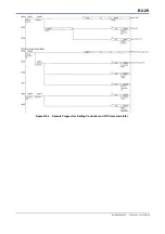
Страница 110: ...B4 2 IM 34M06H62 02E 2nd Edition June 2008 00 Figure B4 1 Sample Program Component for Setting Setup Parameters 2 5...
Страница 111: ...B4 3 IM 34M06H62 02E 2nd Edition June 2008 00 Figure B4 1 Sample Program Component for Setting Setup Parameters 3 5...
Страница 112: ...B4 4 IM 34M06H62 02E 2nd Edition June 2008 00 Figure B4 1 Sample Program Component for Setting Setup Parameters 4 5...
Страница 113: ...B4 5 IM 34M06H62 02E 2nd Edition June 2008 00 Figure B4 1 Sample Program Component for Setting Setup Parameters 5 5...
Страница 118: ...Blank Page...
Страница 130: ...Blank Page...
Страница 204: ...Blank Page...
Страница 215: ...C8 1 IM 34M06H62 02E 2nd Edition June 2008 00 C8 Alarm Function This chapter describes the alarm function of the module...
Страница 222: ...Blank Page...
Страница 224: ...Blank Page...
Страница 228: ...Blank Page...
Страница 230: ...Blank Page...
Страница 232: ...Blank Page...
Страница 234: ...Blank Page...
Страница 240: ...Blank Page...
Страница 242: ...Blank Page...
Страница 254: ...Blank Page...
Страница 258: ...Blank Page...
Страница 260: ...Blank Page...


