


A2-2
IM 34M06H62-02E
3rd Edition : Jul.16, 2015-00
A2.3 General
Specifications
Table A2.2 lists the general specifications of the F3CU04-0S and F3CU04-1S
temperature control and PID modules.
Table A2.2 General Specifications
Item
Specification
F3CU04-0S
F3CU04-1S
Number of loops
4
Isolation Between input terminals
and internal circuit
Isolated by photocouplers and transformers
(tested for 1500 V AC voltage withstanding for 1 minute)
Between input terminals
Between output terminals
and internal circuit
Between output terminals
Not isolated.
Alarm types
12 types of alarm:
Upper input limit, lower input limit, upper deviation limit, lower deviation limit,
upper/lower deviation limit, and deviation range, all with or without waiting
Number of alarm outputs (input relays)
4 points per loop (only alarms 1 and 2 have input relays)
Alarm delay timer
Yes
Warm-up time
30 minutes min.
Max. allowable ambient temperature
change rate
*1
10
C/h max.
Mounting position
Horizontal or inverted orientation not allowed
External connection
One 18-point terminal block with
M3.5 screws
Two 18-point terminal blocks with
M3.5 screws
External dimensions
* 2
28.9 (W) x 100 (H) x 106.1 (D) mm
58 (W) x 100 (H) x 106.1 (D) mm
Current consumption
460 mA at 5 V DC
470 mA at 5 V DC
Weight
200 g
350 g
*1: The stated accuracy for the reference junction for thermocouple input deteriorates if the ambient temperature change
exceeds this rate.
*2: External dimensions excluding protrusions (for details, see the External Dimensions drawing).
A2.4
Input Specifications
Table A2.3 lists the input specifications of the F3CU04-0S and F3CU04-1S temperature
control and PID modules.
Table A2.3 Input Specifications
Item
Specification
F3CU04-0S
F3CU04-1S
Input sampling period
*1
200ms for 4 loops, or 100ms for 2 loops
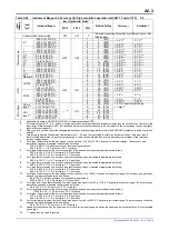
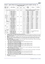
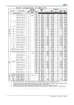
Input types and ranges
See Table A2.4, “Instrument Range and Accuracy”.
Individual inputs separately configurable by software or
collectively by hardware
Thermocouple input : 15 ranges
RTD input
: 9 ranges
DC voltage input
: 6 ranges
Burnout detection
Thermocouples or RTDs are checked for burnout.
Up-scale, down-scale, or none may be selected.
Detection
current
Thermocouple
100 nA max.
RTD
100 nA max.
Input insulation resistance
1 M
min.
Allowable signal
Source resistance
Thermocouple or DC mV input
250
max.
DC voltage input
2 k
max.
Allowable wiring
resistance
RTD
10
max. per wire
(three wires must have the same resistance)
Measuring current
RTD
Approx. 270
μ
A
Reference junction
Compensation
Thermocouple
*2
2.0
C (0 to 55
C)
Allowable input voltage range
-20 to 20 V DC
Noise reduction
*3*4
Common mode
120 dB (50/60 Hz) min.
Normal mode
40 dB (50/60 Hz) min.
Effect of ambient temperature
0.01%/
C or
1
μ
V/
C, whichever is greater
*1: If input sampling period is set to 100 ms for 2 loops, only loops 1 and 2 are available.
*2: This value assumes that all input terminals are correctly wired (that is, solderless termination, wire diameters and
connections are correct).
*3: This value assumes that the power supply frequency is correctly selected.
*4: This module continues to operate at a input accuracy of ±0.5% max. of F.S. during the radiated electromagnetic field test.
Содержание F3CU04-0S
Страница 2: ...Blank Page...
Страница 18: ...Blank Page...
Страница 32: ...Blank Page...
Страница 34: ...Blank Page...
Страница 50: ...Blank Page...
Страница 90: ...Blank Page...
Страница 97: ...B3 7 IM 34M06H62 02E 2nd Edition June 2008 00 Figure B3 2 Sample Program for Setting Controller Parameters 2 2...
Страница 100: ...B3 10 IM 34M06H62 02E 2nd Edition June 2008 00 Figure B3 3 Sample Program for Setting I O Parameters 2 3...
Страница 101: ...B3 11 IM 34M06H62 02E 2nd Edition June 2008 00 Figure B3 3 Sample Program for Setting I O Parameters 3 3...
Страница 110: ...B4 2 IM 34M06H62 02E 2nd Edition June 2008 00 Figure B4 1 Sample Program Component for Setting Setup Parameters 2 5...
Страница 111: ...B4 3 IM 34M06H62 02E 2nd Edition June 2008 00 Figure B4 1 Sample Program Component for Setting Setup Parameters 3 5...
Страница 112: ...B4 4 IM 34M06H62 02E 2nd Edition June 2008 00 Figure B4 1 Sample Program Component for Setting Setup Parameters 4 5...
Страница 113: ...B4 5 IM 34M06H62 02E 2nd Edition June 2008 00 Figure B4 1 Sample Program Component for Setting Setup Parameters 5 5...
Страница 118: ...Blank Page...
Страница 130: ...Blank Page...
Страница 204: ...Blank Page...
Страница 215: ...C8 1 IM 34M06H62 02E 2nd Edition June 2008 00 C8 Alarm Function This chapter describes the alarm function of the module...
Страница 222: ...Blank Page...
Страница 224: ...Blank Page...
Страница 228: ...Blank Page...
Страница 230: ...Blank Page...
Страница 232: ...Blank Page...
Страница 234: ...Blank Page...
Страница 240: ...Blank Page...
Страница 242: ...Blank Page...
Страница 254: ...Blank Page...
Страница 258: ...Blank Page...
Страница 260: ...Blank Page...


