


C1-5
IM 34M06H62-02E
2nd Edition : June 2008-00
Table C1.4 Parameters Related to Cascade Control
Data Position Number
Symbol
Description
Unit
Data Range
Default
Value Attribute Stored
See
Also
Loop1 Loop2 Loop3 Loop4
101
301
501
701
PVIN
Input process value
Industrial
unit
-5 to 105% of (SL to SH)
—
RO
—
C3
102
302
502
702
PV
Process value
Industrial
unit
-5 to 105% of (PRL to
PRH)
—
RO
—
103
303
503
703
CSP
Control set point
Industrial
unit
PRL to PRH
—
RO
—
C4
104
304
504
704
HOUT
Control output
%
OL to OH: for
single output
0 to OH: for
heating/cooling output
—
RO
—
C2
C7.1
305
705
COUT
Cooling control
output
%
0 to OL: For
heating/cooling output
—
RO
—
321
721
RUN/STP Run/stop selection
None
0: Stop; 1: Run
0
RW
—
C7.1
322
722 A/M/C
Automatic/manual/
cascade selection
None
0: Automatic, 1: Manual
2: Cascade
*1
0 RW —
C7.2
C7.4
124
524
RMT/LOC
Remote/local
selection
None
0: Local
1: Remote
0 RW —
C7.3
125 325 525 725 EXPV/PV
External/normal
input selection
None
0: Normal input
1: External input
0 RW —
C3.12
326
726 EXOUT/OUT
External/normal
output selection
None
0: Normal output
1: External output
0 RW —
C2.6
128 328 528 728 SPNO
SP number
selection
None
1 to 4
1
RW
—
C4.1
131 331 531 731 EXPV External
input
Industrial
unit
-5 to 105% of (SL to SH)
SL
RW
—
C3.12
133
533
RSP
Remote set point
Industrial
unit
PRL to PRH
PRL
RW
—
C4.2
334 734 MOUT
Manual
output
%
OL to OH: for
single output
0 to OH: for
heating/cooling output
0 RW —
C7.2
C7.4
335 735
MOUTC
Manual cooling
output
%
0 to OL
0
RW
—
336
736
EXOUT
External output
%
-5.0 to 105.0%
0
RW
—
C2.6
*1
The controller mode must be set to Cascade Control before Automatic/Manual/Cascade Selection (A/M/C) can be
set to 2 (Cascade). In cascade control mode, operation proceeds according to the setup for the even-numbered
loop (2 or 4).
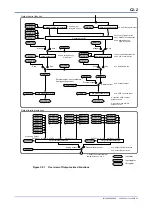
In cascade control mode, controller loops 1 and 2 or loops 3 and 4 form a pair, where the
odd-numbered loop (1 or 3) is the primary loop and the even-numbered loop (2 or 4) is
the secondary loop, and the output from the primary loop is used as the control set point
for the secondary loop.
The control and computation function of the primary loop controls its output so that the
control set point for the secondary loop will not change suddenly when a transition is
made from manual or automatic mode to cascade mode. This is called the tracking
function. The control method is always PID control.
In cascade control mode, the SP-related functions of the secondary loop use the output
from the primary loop as its control set point, and thus remote setting function is not
available.
For details on cascade control operation, see Section C1.2.1, "Cascade Control
Operation." For details on each functional block, see Sections C3, "PV-related
Functions," C4, "SP-related Functions," C6, "Control and Computation Function," and
C2, "Output-related Functions."
TIP
Cascade control is a kind of feedback control system where controllers are connected serially so that
the output from one controller changes the set point of the next controller. It is useful in situations where
it is desirable to minimize impact from external disturbances.
Содержание F3CU04-0S
Страница 2: ...Blank Page...
Страница 18: ...Blank Page...
Страница 32: ...Blank Page...
Страница 34: ...Blank Page...
Страница 50: ...Blank Page...
Страница 90: ...Blank Page...
Страница 97: ...B3 7 IM 34M06H62 02E 2nd Edition June 2008 00 Figure B3 2 Sample Program for Setting Controller Parameters 2 2...
Страница 100: ...B3 10 IM 34M06H62 02E 2nd Edition June 2008 00 Figure B3 3 Sample Program for Setting I O Parameters 2 3...
Страница 101: ...B3 11 IM 34M06H62 02E 2nd Edition June 2008 00 Figure B3 3 Sample Program for Setting I O Parameters 3 3...
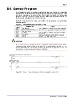
Страница 110: ...B4 2 IM 34M06H62 02E 2nd Edition June 2008 00 Figure B4 1 Sample Program Component for Setting Setup Parameters 2 5...
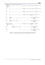
Страница 111: ...B4 3 IM 34M06H62 02E 2nd Edition June 2008 00 Figure B4 1 Sample Program Component for Setting Setup Parameters 3 5...
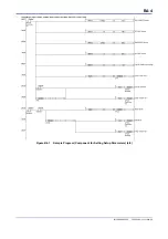
Страница 112: ...B4 4 IM 34M06H62 02E 2nd Edition June 2008 00 Figure B4 1 Sample Program Component for Setting Setup Parameters 4 5...
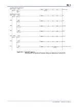
Страница 113: ...B4 5 IM 34M06H62 02E 2nd Edition June 2008 00 Figure B4 1 Sample Program Component for Setting Setup Parameters 5 5...
Страница 118: ...Blank Page...
Страница 130: ...Blank Page...
Страница 204: ...Blank Page...
Страница 215: ...C8 1 IM 34M06H62 02E 2nd Edition June 2008 00 C8 Alarm Function This chapter describes the alarm function of the module...
Страница 222: ...Blank Page...
Страница 224: ...Blank Page...
Страница 228: ...Blank Page...
Страница 230: ...Blank Page...
Страница 232: ...Blank Page...
Страница 234: ...Blank Page...
Страница 240: ...Blank Page...
Страница 242: ...Blank Page...
Страница 254: ...Blank Page...
Страница 258: ...Blank Page...
Страница 260: ...Blank Page...


