


B3-18
IM 34M06H62-02E
2nd Edition : June 2008-00
B3.4 Operation
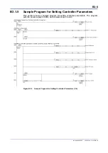
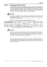
Once you have completed the setup described in Sections B3.1, “Setting Controller
Parameters,” B3.2, "Setting I/O Parameters," and B3.3, “Setting Operation Parameters”,
the module is ready for operation. Start module operation in manual or automatic mode
by writing to the RUN/STP and A/M/C registers. To operate in Manual mode, specify an
output level using the Manual Output (MOUT) register.
For information on SP number selection, remote set point, and other operation control
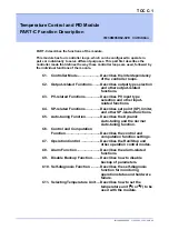
functions, see Section C7, "Operation Control."
Table B3.15 Operation Control Parameters
Data Position Number
Symbol Description Unit Data
Range
Default
Value Attribute Stored
See
Also
Loop1 Loop2 Loop3 Loop4
121
321
521
721
RUN/STP
Run/stop selection
None
0: Stop
1: Run
0
RW
—
C7.1
122
322
522
722
A/M/C
Automatic/manual
/cascade selection
*!
None
0: Automatic
1: Manual
2: Cascade (only
valid for the
even-numbered loop
in cascade control
mode)
0
RW
—
C7.2
C7.4
124
324
524
724
RMT/LOC
Remote/local
selection
None
0: Local, 1: Remote
0
RW
—
C7.3
128
328
528
728
SPNO
SP number selection
None
1 to 4
1
RW
—
C4.1
133
333
533
733
RSP
Remote set point
Industrial
unit
PRL to PRH
PRL
RW
—
C4.2
134
334
534
734
MOUT
Manual output
(for single output or
heating output in
heating/cooling
control)
%
OL to OH: for single
output;
0 to OH: for
heating/cooling
control
0
RW
—
C7.2
C7.4
*1: The controller mode must be set to Cascade Control before the ‘Cascade’ option can be selected. Set the operation
control parameters of the even-numbered loop (loop 2 or 4) in cascade mode.
Table B3.16 Relationship between Operating Status, Operation Control, and Output Values
Operating
Status
Operation Control
Output Remarks
RUN/STP
A/M/C
Stop 0
0
POUT (and POUTC)
This is the status immediately after power up. In Stop mode,
the stored value of the Preset Output parameter is output.
1
Automatic
1
0
HOUT (and COUT)
Manual 1
MOUT
(and
MOUTC)
Содержание F3CU04-0S
Страница 2: ...Blank Page...
Страница 18: ...Blank Page...
Страница 32: ...Blank Page...
Страница 34: ...Blank Page...
Страница 50: ...Blank Page...
Страница 90: ...Blank Page...
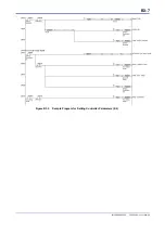
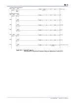
Страница 97: ...B3 7 IM 34M06H62 02E 2nd Edition June 2008 00 Figure B3 2 Sample Program for Setting Controller Parameters 2 2...
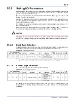
Страница 100: ...B3 10 IM 34M06H62 02E 2nd Edition June 2008 00 Figure B3 3 Sample Program for Setting I O Parameters 2 3...
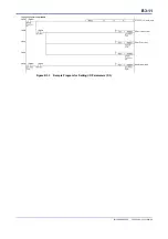
Страница 101: ...B3 11 IM 34M06H62 02E 2nd Edition June 2008 00 Figure B3 3 Sample Program for Setting I O Parameters 3 3...
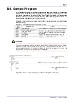
Страница 110: ...B4 2 IM 34M06H62 02E 2nd Edition June 2008 00 Figure B4 1 Sample Program Component for Setting Setup Parameters 2 5...
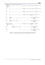
Страница 111: ...B4 3 IM 34M06H62 02E 2nd Edition June 2008 00 Figure B4 1 Sample Program Component for Setting Setup Parameters 3 5...
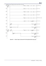
Страница 112: ...B4 4 IM 34M06H62 02E 2nd Edition June 2008 00 Figure B4 1 Sample Program Component for Setting Setup Parameters 4 5...
Страница 113: ...B4 5 IM 34M06H62 02E 2nd Edition June 2008 00 Figure B4 1 Sample Program Component for Setting Setup Parameters 5 5...
Страница 118: ...Blank Page...
Страница 130: ...Blank Page...
Страница 204: ...Blank Page...
Страница 215: ...C8 1 IM 34M06H62 02E 2nd Edition June 2008 00 C8 Alarm Function This chapter describes the alarm function of the module...
Страница 222: ...Blank Page...
Страница 224: ...Blank Page...
Страница 228: ...Blank Page...
Страница 230: ...Blank Page...
Страница 232: ...Blank Page...
Страница 234: ...Blank Page...
Страница 240: ...Blank Page...
Страница 242: ...Blank Page...
Страница 254: ...Blank Page...
Страница 258: ...Blank Page...
Страница 260: ...Blank Page...


