


C2-19
IM 34M06H62-02E
2nd Edition : June 2008-00
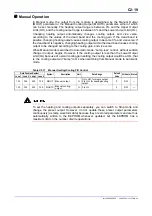
Manual Operation
In Manual mode, the output from the module is determined by the Manual Output
(MOUT) parameter or the Manual Cooling Output (MOUTC) parameter, either of which
can be set manually. The heating output range is between 0% and the Upper Output
Limit (OH), and the cooling output range is between 0% and the Lower Output Limit (OL).
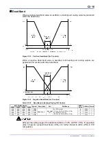
Changing heating output automatically changes cooling output, and vice versa,
according to the values of the dead band and the cooling gain. If the dead band is
positive, changing heating output causes cooling output to become 0%, and vice versa. If
the dead band is negative, changing heating output within the dead band causes cooling
output to be changed according to the cooling gain, and vice versa.
When Manual mode is switched to Automatic mode, “bump-less” control, without sudden
change in output, begins. However, if the cooling output is less than the Lower Output
Limit (OL) because of a small cooling gain setting, the cooling output would be at OL, that
is, the cooling output will “bump” to OL when switching from Manual mode to Automatic
mode.
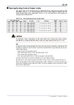
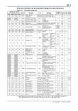
Table C2.17 Manual Heating/Cooling PID Control
Data Position Number
Symbol Description Unit
Data Range
Default
Value
Attribute Stored
Loop 1 Loop 2 Loop 3 Loop 4
134 334 534 734 MOUT
Manual
output
%
OL to OH: for single output
0 to OH: for heating/cooling
output
0 RW
—
135 335 535 735 MOUTC
Manual cooling
output
%
0 to OL
0
RW
—
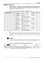
To set the heating and cooling outputs separately, you can switch to Stop mode and
change the preset output. However, do not update these preset output parameters
continuously (as ramp waveform data) because they are stored parameters and are thus
automatically written to the EEPROM whenever updated, but the EEPROM has a
maximum limit on the number of write operations.
Содержание F3CU04-0S
Страница 2: ...Blank Page...
Страница 18: ...Blank Page...
Страница 32: ...Blank Page...
Страница 34: ...Blank Page...
Страница 50: ...Blank Page...
Страница 90: ...Blank Page...
Страница 97: ...B3 7 IM 34M06H62 02E 2nd Edition June 2008 00 Figure B3 2 Sample Program for Setting Controller Parameters 2 2...
Страница 100: ...B3 10 IM 34M06H62 02E 2nd Edition June 2008 00 Figure B3 3 Sample Program for Setting I O Parameters 2 3...
Страница 101: ...B3 11 IM 34M06H62 02E 2nd Edition June 2008 00 Figure B3 3 Sample Program for Setting I O Parameters 3 3...
Страница 110: ...B4 2 IM 34M06H62 02E 2nd Edition June 2008 00 Figure B4 1 Sample Program Component for Setting Setup Parameters 2 5...
Страница 111: ...B4 3 IM 34M06H62 02E 2nd Edition June 2008 00 Figure B4 1 Sample Program Component for Setting Setup Parameters 3 5...
Страница 112: ...B4 4 IM 34M06H62 02E 2nd Edition June 2008 00 Figure B4 1 Sample Program Component for Setting Setup Parameters 4 5...
Страница 113: ...B4 5 IM 34M06H62 02E 2nd Edition June 2008 00 Figure B4 1 Sample Program Component for Setting Setup Parameters 5 5...
Страница 118: ...Blank Page...
Страница 130: ...Blank Page...
Страница 204: ...Blank Page...
Страница 215: ...C8 1 IM 34M06H62 02E 2nd Edition June 2008 00 C8 Alarm Function This chapter describes the alarm function of the module...
Страница 222: ...Blank Page...
Страница 224: ...Blank Page...
Страница 228: ...Blank Page...
Страница 230: ...Blank Page...
Страница 232: ...Blank Page...
Страница 234: ...Blank Page...
Страница 240: ...Blank Page...
Страница 242: ...Blank Page...
Страница 254: ...Blank Page...
Страница 258: ...Blank Page...
Страница 260: ...Blank Page...


