


C2-13
IM 34M06H62-02E
2nd Edition : June 2008-00
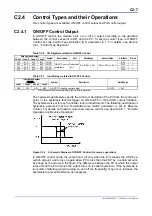
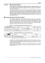
C2.4.3 Heating/Cooling PID Control
In Heating/Cooling PID Control, the module computes its output according to the
deviation between the control set point (CSP) and the PV, and outputs the PID
computation result as heating and cooling outputs. To select Heating/Cooling PID
Control, set the Control Type Selection (OT) parameter to 2. For details, see Section
C2.1, “Control Type Selection."
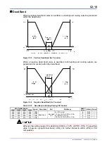
A large PID computation result is output as a heating output, whilst a small PID
computation result is output as a cooling output. A dead band, with no heating and
cooling outputs, can be defined using the Dead Band (DB) parameter. If DB is set to a
negative value, both heating and cooling outputs are generated in the dead band. If the
heating and cooling capacities of a process differ, you can define a cooling gain to
balance the heating and cooling control loop gains.
Figure C2.7 Heating/Cooling Operation in P Control
TIP
Heating and cooling output values are calculated as follows:
- Heating output = (PID computation result - dead band [%]/2 - 50%) x 2
- Cooling output = (50% - PID computation result - dead band [%]/2) x 2 x cooling gain
where dead band [%] is converted from industrial unit to percentage as follows:
Dead band [%] = ((dead band in industrial unit)/(PRH - PRL) x 100%) x 100%/(proportional band x 2)
TIP
In P control, the PID computation result is obtained as follows:
PID computation result = 100/proportional band x (CSP - PV) + manual reset value/2 + 50%
where 50% is added so that both the heating and cooling output values will be 0 when the deviation
(CSP - PV) is 0. This 50% is not added in PID control.
Содержание F3CU04-0S
Страница 2: ...Blank Page...
Страница 18: ...Blank Page...
Страница 32: ...Blank Page...
Страница 34: ...Blank Page...
Страница 50: ...Blank Page...
Страница 90: ...Blank Page...
Страница 97: ...B3 7 IM 34M06H62 02E 2nd Edition June 2008 00 Figure B3 2 Sample Program for Setting Controller Parameters 2 2...
Страница 100: ...B3 10 IM 34M06H62 02E 2nd Edition June 2008 00 Figure B3 3 Sample Program for Setting I O Parameters 2 3...
Страница 101: ...B3 11 IM 34M06H62 02E 2nd Edition June 2008 00 Figure B3 3 Sample Program for Setting I O Parameters 3 3...
Страница 110: ...B4 2 IM 34M06H62 02E 2nd Edition June 2008 00 Figure B4 1 Sample Program Component for Setting Setup Parameters 2 5...
Страница 111: ...B4 3 IM 34M06H62 02E 2nd Edition June 2008 00 Figure B4 1 Sample Program Component for Setting Setup Parameters 3 5...
Страница 112: ...B4 4 IM 34M06H62 02E 2nd Edition June 2008 00 Figure B4 1 Sample Program Component for Setting Setup Parameters 4 5...
Страница 113: ...B4 5 IM 34M06H62 02E 2nd Edition June 2008 00 Figure B4 1 Sample Program Component for Setting Setup Parameters 5 5...
Страница 118: ...Blank Page...
Страница 130: ...Blank Page...
Страница 204: ...Blank Page...
Страница 215: ...C8 1 IM 34M06H62 02E 2nd Edition June 2008 00 C8 Alarm Function This chapter describes the alarm function of the module...
Страница 222: ...Blank Page...
Страница 224: ...Blank Page...
Страница 228: ...Blank Page...
Страница 230: ...Blank Page...
Страница 232: ...Blank Page...
Страница 234: ...Blank Page...
Страница 240: ...Blank Page...
Страница 242: ...Blank Page...
Страница 254: ...Blank Page...
Страница 258: ...Blank Page...
Страница 260: ...Blank Page...


