32
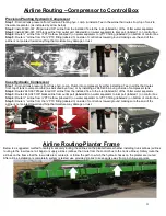
Airline Routing
–Compressor to Control Box
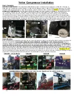
Yetter Compressor
Step 1:
Install 2940-367 250psi rated 3/8 airline from compressor outlet to inlet (water trap side labeled A) of water separator.
Step 2:
Install 2940-
345 3/8” black airline from outlet port of water separator (labeled B) to inlet port (labeled 1) on control box.
Step 3:
Route ¼” airline from ¼”PTC elbow (labeled C) on water separator to ¼”PTC fitting (labeled 2) on bottom of control box.
Step 4:
Ro
ute ¼” airline from the ¼”PTC fitting (labeled 3) on side of control box toward the ground making sure the end of the
airline is not pointed toward anything that moisture may damage or rust.
Yetter Compressor Communication Harness
Step 1:
Install 2940-181 compressor solenoid/switch harness; male 2 pin connector installs into female connector on On/Off
solenoid, female 2 pin connector installs into male 2 pin connector on pressure switch.
Step 2:
Connect the 2940-189 (10ft) control harness to 4 pin connector of the 2940-181 & route to control box. If more length is
needed, call Yetter & order more. (2940-182 is 20ft length; 2940-189 is 10ft length)
Step 3:
Connect the 2940-182 or 2940-189 into the 4 pin female connector on side of the control box.
John Deere Hydraulic Compressor
Step 1:
Locate the manifold block on the hyd. comp., drain air pressure from tank/manifold block, & remove gauge/pipe plug.
Step 2:
If pipe plug equipped, install 2940-408 3/8 PTC elbow where plug was removed. If gauge equipped, install 2940-374
adaptor. Male end gets Teflon tape & installs on manifold block, gauge installs in rearward facing female end, & 2940-408
3/8PTC elbow installs in remaining end.
Step 3:
Install 2940-367-250psi rated 3/8 airline from the 3/8 PTC elbow fitting to the inlet port (labeled A) of water separator.
Step 4:
Route 2940-345 black
3/8”airline from outlet port (labeled B) of water separator to inlet port (labeled 1) on control box.
Step 5:
Route ¼” airline from ¼”PTC elbow (labeled C) on water separator to ¼”PTC fitting (labeled 2) on bottom of control box.
Step 6:
Route ¼” airline from the ¼”PTC fitting (labeled 3) on side of control box toward the ground making sure the end of the
airline is not pointed toward anything that moisture may damage or rust.
PIPE PLUG ONLY
GAUGE INSTALLED
Содержание GERMINATE UNIFORMITY 2940
Страница 35: ...35 6 Row Airline Diagram 6 11 or 6 12 Split Row Airline Diagram...
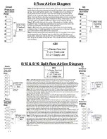
Страница 36: ...36 8 Row Airline Diagram 8 15 8 16 Split Row Airline Diagram...
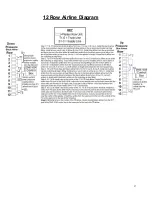
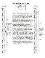
Страница 37: ...37 12 Row Airline Diagram...
Страница 39: ...39 16 Row Airline Diagram...
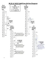
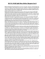
Страница 40: ...40 16 31 16 32 Split Row Airline Diagram...
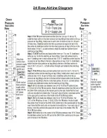
Страница 42: ...42 24 Row Airline Diagram...
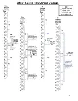
Страница 43: ...43 24 47 24 48 Row Airline Diagram...
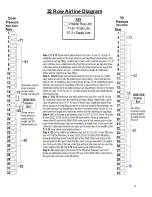
Страница 45: ...45 32 Row Airline Diagram...
Страница 46: ...46 36 Row Airline Diagram...
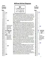
Страница 47: ...47 48 Row Airline Diagram...
Страница 48: ...48 54 Row Airline Diagram...
Страница 78: ...78 HYDRAULIC PUMP 2940 545 PARTS IDENTIFICATION PART REFERENCE ONLY...
Страница 82: ...82 2565 983_REV_B 09 21...

