30
Yetter Hydraulic Compressor Installation
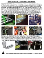
Step 3: Hydraulic Hose and Fittings Installation to the Compressor
Tool required: An assortment of standard wrenches & crescent wrench.
A)
Remove the cap from the
– 6 port (also labeled P on the Hydraulic Control Block) & install the 2515-431 – 6 ORB (O-Ring
Boss) to
– 6 JIC straight adaptor fitting so that the O-Ring end goes into the hydraulic block & the JIC end faces away from
the block. Install 1) 2515-831 3/8
– 6 10ft hydraulic hose to that fitting.
B)
Remove the cap from the
– 8 port (also labeled T on the Hydraulic Control Block) & install the 2515-833 – 8 ORB to – 8 JIC
straight adaptor fitting so that the O-Ring end goes into the hydraulic block & the JIC end faces away from the block. Install
the 2515-832 ½
– 8 10ft hydraulic hose to that fitting.
C)
Remove cap plug from
– 4 port on the motor (this is the Case Drain)using a 3/16 hex key wrench if equipped with threaded
plug (may also have rubber plug) & install the 2515- 848
–4 ORB to – 6 JIC 90 degree
adaptor fitting so that the O-Ring end
goes into the hydraulic motor & the JIC end faces downward. Install 1) 2515-831 3/8
– 6 10ft hydraulic hose to that fitting.
Control Box to Yetter Compressor Wiring Installation
Step 1:
Install the 2940-181 Solenoid/Pressure Switch Control Harness on the compressor.
Step 2:
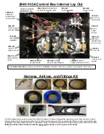
Install the 2940-189 between the 2940-181 and the 4 pin connector on the side of the 2940-103A control box.
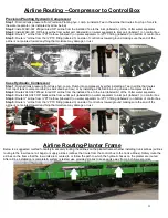
2940-114 Stand Alone Compressor Wiring Kit Installation
Step 1:
Install the 2940-518 Cab Switch harness in the tractor cab. Mount the Switch in an area easily accessable. The 2 bare
wires need spliced to the OEM Switched Power Connector (not supplied), & the female 2 pin Deutsch routes to tractor hitch.
Step 2:
From the 2 pin female Deutsch of the 2940-518 at the hitch, install as many 2940-154 (30ft extension) harnesses as
need to reach the compressor.
Step 3:
Install the 2940-525 at compressor as labeled in photo below. Install the 2940-154 into the remaining open connector.
Содержание GERMINATE UNIFORMITY 2940
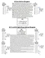
Страница 35: ...35 6 Row Airline Diagram 6 11 or 6 12 Split Row Airline Diagram...
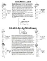
Страница 36: ...36 8 Row Airline Diagram 8 15 8 16 Split Row Airline Diagram...
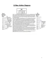
Страница 37: ...37 12 Row Airline Diagram...
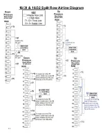
Страница 39: ...39 16 Row Airline Diagram...
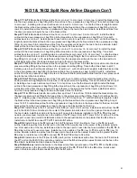
Страница 40: ...40 16 31 16 32 Split Row Airline Diagram...
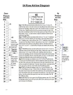
Страница 42: ...42 24 Row Airline Diagram...
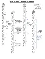
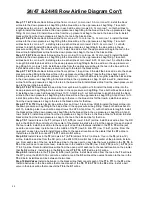
Страница 43: ...43 24 47 24 48 Row Airline Diagram...
Страница 45: ...45 32 Row Airline Diagram...
Страница 46: ...46 36 Row Airline Diagram...
Страница 47: ...47 48 Row Airline Diagram...
Страница 48: ...48 54 Row Airline Diagram...
Страница 78: ...78 HYDRAULIC PUMP 2940 545 PARTS IDENTIFICATION PART REFERENCE ONLY...
Страница 82: ...82 2565 983_REV_B 09 21...

