15
Control Box
The 2940-103A control box communicates between the 2940-112A VDM & 2940-653 Thrasher, dispenses air out of quick
exhaust regs that are fed by little fill/dump valves as the operator sends commands. The VDM is the valve drive module that is
programmed to carry out each function of the system. The Thrasher uses a WiFi signal or ISOBUS to communicate commands
by the operator to execute thru the VDM.
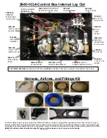
2940-103A Control Box External Lay Out
WHEEL TRACK (WT) DOWN PRESSURE PORT
- Safely route black airline from the WT port to the tee in the center section of the
planter’s down pressure trunk airline. The down pressure on the center section residue managers (RM) or RM/Coulter Combo can be
adjusted separately than the wing/outer sections down pressure to make up for tractor/planter tire compaction. WT should be set 2-5
psi heavier than RD. If the WT port is not used, install a plug (2940-352) to prevent air loss.
RESIDUE MANAGER DOWN (RD) PRESSURE PORT
- Safely route black airline from the RD port to the open port on each tee
installed in the trunk airline on each wing/outer sections of the planter. This port dispenses down pressure to the RM or RM/Coulter
Combos on the wing/side of the planter.
RESIDUE MANAGER UP (RU) PRESSURE PORT
- Safely route blue airline from the RU port to each tee on each section of the
planter
’s up pressure trunk airline. This port dispenses up pressure to each RM or RM/Coulter Combo on the planter.
WATER SEPARATOR INLET
-
Install the ¼” airline from the bottom of the water separator into this port.
WATER SEPARATOR OUTLET
-
Install ¼” airline in this port, route toward the ground. (drain’s condensation from water separator)
MAIN AIR SUPPLY INLET-
Plumb the 2940-
367 250psi rated 3/8” airline from the hydraulic compressor to the inlet (water trap side)
of the water separator/regulator assembly. Plumb 2940-
345 3/8” black airline from outlet (regulator side) of the water
separator/regulator assembly to this port. Ensure the regulator is set to 100-120psi by reading the gauge.
COMPRESSOR COMMUNICATION
– Install the 2940-181 Compressor Solenoid/Switch Harness at the compressor. Use 2940-182
(20FT) &/or 2940-189 (10FT) extension harnesses to reach the control box & install into this port. Used only if application uses a
Yetter Hydraulic Compressor.
(see page 28)
POWER HARNESS CONNECTION
- Depending on application, route 2940-164A or 2940-165A AUX PWR cable from rear of the
tractor to this female connector. If the control box is mounted at the rear of the planter, 2940-170A, 2940-171A, or 2940-430A AUX
PWR extensions will route to this female connector.
2940-654 MIDAC TO THRASHER HARNESS
– Connects the communication/power supply from the Midac to the Thrasher
2940-653 – JCA THRASHER MODULE
(MOUNTED ON TOP OF THE BOX)
2940-654 – MIDAC TO THRASHER
COMMUNICATION HARNESS
POWER
HARNESS
CONNECTOR
ISOBUS
CONNECTION
COMPRESSOR
COMMUNICATION
THRASHER TO
VDM
CONNECTOR
2940-408
AIR SUPPLY
INLET ELBOW
WATER
SEPARATOR
OUTLET
WATER
SEPARATOR
INLET
RU – ALL ROWS
UPPRESSURE
RD – WING ROWS
DOWN PRESSURE
WT – CENTER ROWS
DOWN PRESSURE
Содержание GERMINATE UNIFORMITY 2940
Страница 35: ...35 6 Row Airline Diagram 6 11 or 6 12 Split Row Airline Diagram...
Страница 36: ...36 8 Row Airline Diagram 8 15 8 16 Split Row Airline Diagram...
Страница 37: ...37 12 Row Airline Diagram...
Страница 39: ...39 16 Row Airline Diagram...
Страница 40: ...40 16 31 16 32 Split Row Airline Diagram...
Страница 42: ...42 24 Row Airline Diagram...
Страница 43: ...43 24 47 24 48 Row Airline Diagram...
Страница 45: ...45 32 Row Airline Diagram...
Страница 46: ...46 36 Row Airline Diagram...
Страница 47: ...47 48 Row Airline Diagram...
Страница 48: ...48 54 Row Airline Diagram...
Страница 78: ...78 HYDRAULIC PUMP 2940 545 PARTS IDENTIFICATION PART REFERENCE ONLY...
Страница 82: ...82 2565 983_REV_B 09 21...

