17
Installation Guide Using a Yetter Compressor
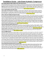
*For installation using a John Deere Hydraulic Compressor installation, see page 17, a Precision Planting Hydraulic
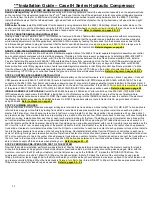
Compressor, see page 18, or a Case IH Hydraulic Compressor, see page 19.
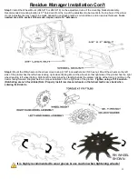
STEP 1: RESIDUE MANAGER (RM) OR RM/COULTER COMBO INSTALLATION
Residue Manager Only:
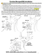
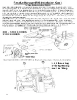
Install RM Assemblies securing with mounting hardware. Install wheel mount assembly on the adjustment tube so the
top hole of the wheel mount aligns to the 4
th
or 5
th
hole down from the top of the adjustment tube for conventional tillage/mellow soils, 5
th
or 6
th
hole from the top for no till/minimum till conditions. Install wheels on wheel mounts using hardware from the 2966-119 bolt bag. Install the RM
wheels so that the left wheel leads, right wheel trails on the left side of planter; the right wheel leads, left wheel trails on right side of planter.
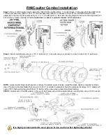
RM/Coulter Combo:
Install the RM/Coulter Combo assembly using hardware from the 2940-128 bolt bag. Mount the coulter blade on the
coulter arm hub & mount the RM wheels using the 5/8 Whiz Lock Nuts. RM wheels on combo units will install in the rear holes on both sides on
all rows. It is recommended to set the coulter blade at seed depth or above.
Refer to diagram on pages 20
– 23
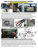
STEP 2: TABLET/ISOBUS IN-CAB INSTALLATION
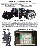
If using a tablet, mount Tablet & 2940-111 RAM Mount in tractor cab. Position Tablet within reach during operation without compromising
safety/visibility from cab. The right rear corner post area is recommended so that operator can see performance of residue managers while
making adjustments. In both applications, install 2940-153A harness by feeding the bare ends thru the harness access hole into the cab. Bare
ends get spliced to plug (not provided) that fits
tractor’s switched power source, splice red wire on 2940-153A to orange wire & splice black
wires together on each harness. Leave the 2 pin connector at the tractor hitch.
Refer to diagram on page 24
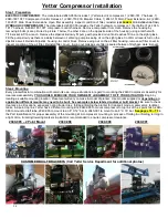
STEP 3: COMPRESSOR & CONTROL BOX INSTALLATION
Control Box Installation:
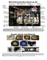
Mount the control box in a safe location with mounts/hardware supplied where the control box can be viewed from
the tractor cab. Install the 2940-415 water separator/regulator assembly near the control box. Measure & cut the 2940-
367 250psi rated 3/8”
airline & install from outlet elbow on the compressor into the 2940-415 inlet (water trap side). Adjust the regulator to allow 100-120psi of air into
inlet of control box. Install
3/8” airline from 2940-415 outlet fitting (regulator side) to control box 3/8 inlet fitting. Route provided ¼” airline from
elbow on bottom of 2940-415 to
¼”PTC fitting on bottom of control box. Route ¼” airline from ¼”PTC fitting on the side of control box toward
the ground, as airline will dispense moisture.
Refer to diagram on pages 25
– 26, 31 – 32
Compressor Installation:
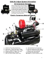
Remove compressor from shipping crate. On Hyd. Compressors, remove the control block & housing to add
provided oil to fill line on sight glass of the Rol-Air pump. Reinstall housing & control block after filling with oil. Locate a suitable mounting
location for the compressor assembly. Placement of the compressor assembly will vary on the make & model of the planter. Use mounts &
hardware supplied or depending on application,
different mounts may need to be built
.
Be sure to check clearance of the compressor in the
mounting location, noting tractor tires while making turns, markers, & folding/unfolding the planter.
Refer to diagram on pages 27
– 30
STEP 4: COMPRESSOR & CONTROL BOX HARNESS INSTALLATION)
Only on Yetter electric compressor installation, install 2940-150 main power cable/breaker (4 gauge cable, 80A breaker) on tractor battery on
the correct terminals, red = po, black = negative
–. Install 2940-151(10ft) & 2940-163(20ft) power cable extensions as needed between
the main power cable/breaker & main power connector on the electric compressor. On all installations, install the 2940-166 VDM power cable
with 40A breaker on the tractor battery on the correct terminals, red = po, black = negative
–. Connect the VDM power extension (2940-
167 or 2940-168) & route to the tractor hitch. Install the AUX PWR Harness, 2940-164A or 2940-165A. The 2 pin connects to the 2940-153A
from the tractor cab, the Anderson power connector connects to the 8 gauge cable that routes to the battery, & the black male 12 pin Deutsch
connector connects to power harness connector on the side of the control box. If the 2940-103A control box is mounted at the back of the
planter, 2940-170A(10ft), 2940-171A(30ft), & 2940-430A(20ft) AUX PWR extensions will be needed. Install the 2940-181 Y harness on the
Yetter compressor. Install the 2940-182 or 2940-189 control harness from the 4 pin end of the 2940-181 Y harness to the 4 pin connector on
the side of the control box.
Refer to diagram on page 24, 28
– 29
ISOBUS HARNESS (IF APPLICABLE)
Install 2940-655 harness to 2940-654 on Yetter control box. Use 2940-657(15ft) & 2940-658(30ft) ext-
ensions to reach where ISOBUS is being tied in. On JD planters, use 2940-659 to plug in at back of planter where terminating resister harness
was located. On RCM I Ag Leader systems, plug into ISOBUS connections near center of planter at Planter Control Module using 2940-662
harness. On RCM II Ag Leader systems, route to tractor hitch & plug into back of tractor using 2940-656.
Refer to diagram on page 26
STEP 5: PLUMBING AIRLINES
A group of airlines that route to residue manager air bags are referred to as trunk airlines. Airline routing from RU, RD, & WT to trunk airline is
referred to as a supply airline. Start by routing trunk airlines: route black (down pressure) & blue (up pressure) airline on each wing/side of
planter. Start at end row of each wing, route airline to last row on wing & install in air bag, black airline = down pressure air bag, blue airline =
up pressure air bag. Follow airline back to end row cutting a tee in each airline at each row. When return back to end row, cut airline to length &
install into air bag. Install airline from each tee at each row & install in air bag for that row. If installing on a split row planter, keep trunk airline
on front rank residue managers on each wing plumbed separate from back rank. When plumbing in WT (wheel track) rows, use center 4 or 6
rows that plant over the tractor & planter wheel tracks. If equipping on a narrow transport planter with 4 center rows & 6 rows are desired on the
WT circuit, tie in the 1 row on each wing/side of the planter closest to the first & last center row. Install a tee in the center of each up pressure
trunk airline. Use tees to route/install blue airline from the RU port on control box to each tee in center of each up pressure trunk airline. Install a
tee into the down pressure trunk airline on the left wing & right wing. Route/install black airline from the RD port on control box to each tee in
center of left & right wing down pressure trunk airline. Install tee in center of center section down pressure trunk airline. Route/install airline from
WT port on control box to tee in the center of down pressure trunk airline on center of planter. If planter is dual rank, connect the trunk airline on
the corn rows to the trunk airline of the bean rows. Use 2940-342 ball valves between corn row trunk airlines & bean row trunk airlines to be
able to shut air supply off to bean rows when planting corn.
Refer to pages 32
– 47
STEP 6: PERFORM A PRE-OPERATION TEST OF THE SYSTEM
Now that the system is installed, perform a pre-operation test. Start by folding/unfolding & lowering/raising the planter checking for slack in
airline & in harnesses at hinge points. Check all electrical connections, cables, & airline making sure nothing was damaged. Next, with the
tractor on, connect to the WiFi with your tablet or pull the Yetter screen up on the ISOBUS VT, & press the ACTIVE SYSTEM icon. The
compressor will turn on, build to 145psi (100-120psi on the cab controller) & shut off. Check the interior of the control box housing (valve,
fittings, & airline) for leaks. Apply 40psi to the RU port & watch your RMs as they should all raise to maximum up travel. Check for leaks on all
up pressure circuits & fittings. When that leak check is finished, turn RU to 0psi & turn RD & WT to 40psi. Check all down pressure airline &
fittings in these circuits for leaks & repair as needed.
Refer to pages 53
– 54
Содержание GERMINATE UNIFORMITY 2940
Страница 35: ...35 6 Row Airline Diagram 6 11 or 6 12 Split Row Airline Diagram...
Страница 36: ...36 8 Row Airline Diagram 8 15 8 16 Split Row Airline Diagram...
Страница 37: ...37 12 Row Airline Diagram...
Страница 39: ...39 16 Row Airline Diagram...
Страница 40: ...40 16 31 16 32 Split Row Airline Diagram...
Страница 42: ...42 24 Row Airline Diagram...
Страница 43: ...43 24 47 24 48 Row Airline Diagram...
Страница 45: ...45 32 Row Airline Diagram...
Страница 46: ...46 36 Row Airline Diagram...
Страница 47: ...47 48 Row Airline Diagram...
Страница 48: ...48 54 Row Airline Diagram...
Страница 78: ...78 HYDRAULIC PUMP 2940 545 PARTS IDENTIFICATION PART REFERENCE ONLY...
Страница 82: ...82 2565 983_REV_B 09 21...


