55
Pre-Field Operation Guide
Con’t
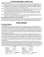
SYSTEM LEAK TESTING:
Step 1:
Power the
Yetter control box, connect tablet to “AIR ADJUST” WiFi & open Yetter app or if ISOUBS application, open
Yetter run page on the ISOBUS VT, & press ACTIVATE SYSTEM. If using planters onboard compressor, make sure
the compressor has run 1 complete cycle, and shut off to make sure there are no leaks at compressor & control box.
Step 2:
With 0psi commanded to the RU, RD, & WT circuits, note the pressure on the compressor tank gauge. Start a stop
watch & after 5 minutes, note the tank pressure. If tank pressure drops more
the 5 psi, check for leaks around/inside
the compressor housing, water separator, & control box. Repair as needed.
Step 3:
Turn the lift pressure (RU) to 40psi, exit the tractor cab, & start at the compressor housing checking all blue airline on
the RU circuit for air leaks. The row cleaners should be in the raised position. Check all fittings, tees, & airline on the
RU circuit. Repair leaks as needed, return to the cab, & turn the lift pressure back to 0psi.
Step 4:
Turn the down pressure (RD) & wheel track (WT) pressure to 40psi, exit the tractor cab, & start at the compressor
housing checking all black airlines on the RD & WT circuit for leaks. The row cleaners should be firmly in the down
position. Check all fittings, tees, & airline on the RD & WT circuits for air leaks. Repair leaks as need, return to the
tractor cab, & turn all circuit pressures to 0psi.
Step 5:
With 40psi commanded in the RU, RD, & WT circuits, note the pressure on the compressor tank gauge. Start a stop
watch & after 5 minutes, note the tank pressure on gauge at the tank. If tank pressure drops more than 10psi, check
for leaks on the row cleaner fittings, tees, and dump valves. Repair as needed.
AIR COMPRESSOR PRE-OPERATING TEST PROCEDURE:
Before beginning this test, run the compressor system leak test and ensure it passes. There should be virtually no leaks in the
tank circuit before performing this test. Use a stop watch to time
the hydraulic compressor’s recovery time. Start time when tank
gauge reaches 125psi & the compressor turns on. Stop the time when compressor shuts off at 145psi. If the time is greater
than 20 seconds, there is a potential
leak, the compressor is worn, or compressor’s RPMs are too slow. Repair as needed.
Proper Settings
Air Pressure Settings
Residue Managers Only
A common question is “What pressures should I start out at?” A good starting pressure setting would be PRESET 2: 35psi Up
Pressure (RU), 30psi Down Pressure (RD), & 32psi Wheel Track (WT). This particular setting will give each row cleaner a nice, sturdy
float. If this pressure setting doesn’t remove enough residue or trenches/digs furrows, adjust the settings accordingly until the row
cleaner is doing exactly what you want it to do. If the row cleaner is trenching, move to a lighter preset, in this case, PRESET 1. If not
enough residue is removed, move to a heavier preset, in this case, PRESET 3
– 5. Once a preset is found or is very close, fine tune
the preset using the +/-1 icons. Each field may require a different setting even though field conditions seem the same. For example, if
you use a setting for one no-till field planting corn in soybean residue, you may find that the setting used for the next field planting corn
in soybean residue in no-till conditions may be different. The reason may be the amount of residue, soil types, moisture amounts, etc.
Residue managers/Coulter Combos
A common question is “What pressures should I start out at?” A good starting pressure setting would be PRESET 3: 30psi Up
Pressure (RU), 35psi Down Pressure (RD), & 37psi Wheel Track (WT). This particular setting will give each row cleaner a nice sturdy
float
If this pressure setting doesn’t remove enough residue or trenches/digs furrows, adjust the settings accordingly until the row
cleaner is doing exactly what you want it to do. If the row cleaner is trenching, move to a lighter preset, in this case, PRESET 1. If not
enough residue is removed, move to a heavier preset, in this case, PRESET 3
– 5. Once a preset is found or is very close, fine tune
the preset using the +/-1 icons. Each field may require a different setting even though field conditions seem the same. For example, if
you use a setting for one no-till field planting corn in soybean residue, you may find that the setting used for the next field planting corn
in soybean residue in no-till conditions may be different. The reason may be the amount of residue, soil types, moisture amounts, etc.
Renaming Presets
Presets can be edited 2 ways: target pressure & preset label. To help the operator better understand which preset to start out with,
renaming the preset label to the planting condition is a good idea. Preset names have a 20 character max limit. If planting corn into corn
stalks, a good name for the preset might be CORN ON CORN. If planting into a variety of tillage conditions, naming your presets for
each condition might be best: NO TILL, STRIP TILL, CONVENTIONAL TILL, etc. Use the renaming of the presets to allow all operators
to have a better understanding of the best starting point for the row cleaner pressures when entering a new field. 1 field that is no-till
with soybean stubble may use different pressures than another field of no-till soybean stubble. Use +/-1 icon in each circuit to fine-tune
the row cleaners to perform exactly how the operator wants them to. Make sure to press
SAVE
after all edits if wanting to keep.
Содержание GERMINATE UNIFORMITY 2940
Страница 35: ...35 6 Row Airline Diagram 6 11 or 6 12 Split Row Airline Diagram...
Страница 36: ...36 8 Row Airline Diagram 8 15 8 16 Split Row Airline Diagram...
Страница 37: ...37 12 Row Airline Diagram...
Страница 39: ...39 16 Row Airline Diagram...
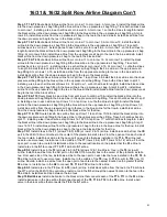
Страница 40: ...40 16 31 16 32 Split Row Airline Diagram...
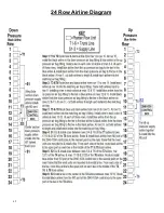
Страница 42: ...42 24 Row Airline Diagram...
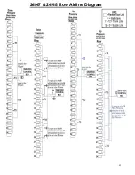
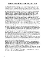
Страница 43: ...43 24 47 24 48 Row Airline Diagram...
Страница 45: ...45 32 Row Airline Diagram...
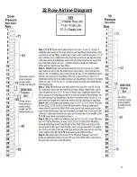
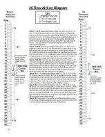
Страница 46: ...46 36 Row Airline Diagram...
Страница 47: ...47 48 Row Airline Diagram...
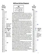
Страница 48: ...48 54 Row Airline Diagram...
Страница 78: ...78 HYDRAULIC PUMP 2940 545 PARTS IDENTIFICATION PART REFERENCE ONLY...
Страница 82: ...82 2565 983_REV_B 09 21...

