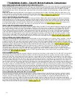
21
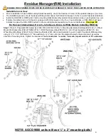
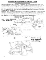
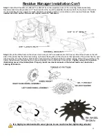
Residue Manager(RM) Installation
ENGAGE THE CYLINDER STOPS ON
THE PLANTER LIFT WHEELS TO “LOCK” THE PLANTER IN THE UP POSITION
Installation overview:
Prior to installation of each RM mounting bracket assembly, check the freedom of motion of the parallel linkage or pivot arm.
The installation process should be done with the planter raised, half folded for transport, & the row units fully extended down.
Install the 2940 RM or RM/Coulter Combo mounting bracket assembly centered & level side to side on each planter row unit.
If planter manufacturer is John Deere & equipped with HD scrapers on the True V opener blades, a 2940-049 kit will need
installed to space the RM or RM/Coulter Combo mounting bracket assembly out to avoid interference.
(See page 60)
For Harvest International, Horsch, John Deere, Kinze, & White Models Installing RM Only
Step 1:
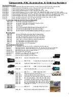
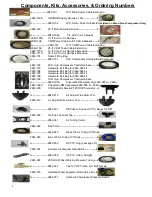
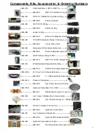
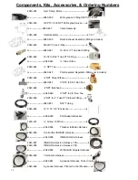
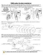
Place 1) Pneumatic RM Assembly (2940-190A OR 2940-192A), 1) Mounting Hardware Bolt Bag (2940-142), 1) Wheel
Mount Weld Assembly (2940-215/2940-216), 1) RH Wheel Assembly (2966-140), 1) LH Wheel Assembly (2966-141), & 1)
Wheel Mount Bolt Bag (2966-119), & 2) Bearing Shields (2967-392) at each planter row unit. Install Pneumatic RM assembly
using 3) ½” X 1-1/2” GR5 bolts, 6) ½” flat washers, & 3) ½” lock nuts. Use the diagram below for hole alignment, as well as
direction of mounting bolts. Tighten the hardware.
Tools needed are ¾ socket, ¾ wrench, impact wrench
, & 10” extension.
NOTE: AGCO 9000 units will use ½” x 2” mounting bolts!
Содержание GERMINATE UNIFORMITY 2940
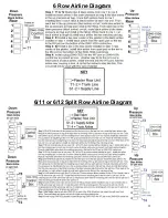
Страница 35: ...35 6 Row Airline Diagram 6 11 or 6 12 Split Row Airline Diagram...
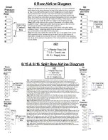
Страница 36: ...36 8 Row Airline Diagram 8 15 8 16 Split Row Airline Diagram...
Страница 37: ...37 12 Row Airline Diagram...
Страница 39: ...39 16 Row Airline Diagram...
Страница 40: ...40 16 31 16 32 Split Row Airline Diagram...
Страница 42: ...42 24 Row Airline Diagram...
Страница 43: ...43 24 47 24 48 Row Airline Diagram...
Страница 45: ...45 32 Row Airline Diagram...
Страница 46: ...46 36 Row Airline Diagram...
Страница 47: ...47 48 Row Airline Diagram...
Страница 48: ...48 54 Row Airline Diagram...
Страница 78: ...78 HYDRAULIC PUMP 2940 545 PARTS IDENTIFICATION PART REFERENCE ONLY...
Страница 82: ...82 2565 983_REV_B 09 21...

