28
Yetter Compressor Installation
Step 1: Preparation
ELECTRIC COMPRESSOR:
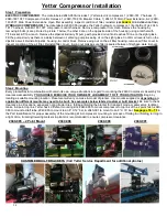
The crate labeled 2940-050A includes 1) Yetter electric compressor, 1) 2940-181 Y harness, 1)
2940-189 10FT Compressor Control Harness, 1) 2940-150 80A Breaker Cable, 1) 2940-151 Main Power Extension, & 2) 2940-
163 20FT Main Power Extensions. Open filter assembly, inspect condition of filter, reinstall.
(SEE PAGE 12 FOR FILTER LOCATION)
HYDRAULIC COMPRESSOR:
The crate labeled 2940-055 includes the Yetter hydraulic compressor, 1 liter bottle of oil, 2940-
181 Y harness, & 2940-189 10FT compressor control harness. Remove compressor from crate. Remove the housing by
removing 6 bolts (4 are pictured in picture 1 below, the other 2 are on the opposite side of the housing) using a ratchet with
7/16 socket & 7/16 wrench. Remove the dipstick & slowly fill pump with provided oil until oil reaches fill line on the sight glass.
Fill the pump slowly as there is a delay between oil entering pump & seeing oil on the sight glass. Confirm oil level is full on the
dipstick as well. Reinstall dipstick, housing, & control block. Remove wing nut on the air filter housing, remove air filter cover, &
inspect condition of the air filter. Reinstall filter, cover, & wing nut making sure filter is sealed between filter base plate & cover.
Step 2: Mounting
Every planter/tractor combination will contain its own unique situations in regard to mounting the 2940 Compressor Assembly for
clearance/accessibility.
YOU SHOULD EXERCISE YOUR OWN BEST JUDGEMENT TO FIT YOUR SITUATION
. Begin by
locating a suitable mounting location. Placement will vary on make & model of planter. Use mounts supplied or
depending on
application different mounts may need to be built. See examples below labeled customer built bracket
. Be sure to check
clearance in all locations, especially noting tractor tires, folding/unfolding the planter for transport mode, marker arms, fertilizer
tanks, & 2-point top link. Yetter has 4 different mounting kits; 2940-085 to mount compressor to top link of the 2 point hitch, 2940-
086 to mount to draft tube, 2940-090 to mount to an 8
” X 12” bar, & 2940-091 to mount to an 8” X 16” bar.
See pages 72
– 73
in
the Part Identification for proper assembly of the mounting kit & compressor mounting. A process of folding & unfolding, turning in
a tight circle, & raising/lowering markers & planter is recommended to ensure compressor clearance.
2940-085
– 2 Point Mount
2940-086
2940-090 2940-091
CUSTOMER BUILT BRACKETS (Call Yetter Service Department for additional photos)
Содержание GERMINATE UNIFORMITY 2940
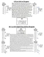
Страница 35: ...35 6 Row Airline Diagram 6 11 or 6 12 Split Row Airline Diagram...
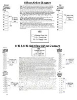
Страница 36: ...36 8 Row Airline Diagram 8 15 8 16 Split Row Airline Diagram...
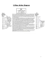
Страница 37: ...37 12 Row Airline Diagram...
Страница 39: ...39 16 Row Airline Diagram...
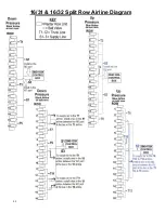
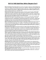
Страница 40: ...40 16 31 16 32 Split Row Airline Diagram...
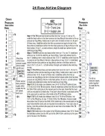
Страница 42: ...42 24 Row Airline Diagram...
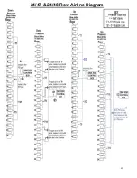
Страница 43: ...43 24 47 24 48 Row Airline Diagram...
Страница 45: ...45 32 Row Airline Diagram...
Страница 46: ...46 36 Row Airline Diagram...
Страница 47: ...47 48 Row Airline Diagram...
Страница 48: ...48 54 Row Airline Diagram...
Страница 78: ...78 HYDRAULIC PUMP 2940 545 PARTS IDENTIFICATION PART REFERENCE ONLY...
Страница 82: ...82 2565 983_REV_B 09 21...


