52
2940 Operation Guide
System Start Up Procedure
Below is the 2940 system startup procedure that should be followed every time the 2940 system is turned on. This will ensure
that component parts of the system are working correctly. If this is the first start up procedure after installation, make sure to
familiarize yourself with cab controller operation first.
Step 1:
Supply switched power to control box (start the tractor or turn the key forward if just testing the system with shop air)
Step 2:
If using Tablet, connect to Air Adjust WiFi & open Yetter App. Press ACTIVATE SYSTEM. If using ISOBUS, open Yetter
run page & press ACTIVATE SYSTEM.
Step 3:
If using Yetter compressor, the compressor should engage (apply hydraulic flow if applicable) to build 145psi & shut off. If
145psi isn’t reached,
see page 53
to make an adjustment to the flow control valve. If Yetter compressor doesn’t run & is below
125psi, check the 40A breaker (& 80A breaker on Yetter electric compressor applications) on tractor battery. Trip breaker & reset
breaker arm firmly back into pocket. If using other OEM compressor, engage compressor & allow compressor to run a complete
cycle & shut off. If using shop air,
unplug onboard compressor’s solenoid & make sure system pressure is at least 100psi.
Step 4:
When compressor has shut off, press a preset (1
– 5) to apply air to the air bags of the residue managers. Make sure the
TANK PSI holds steady. If tank pressure drops & will not hold, turn all pressures (RU, RD, & WT) to 0psi & perform leak check
(
see page 54
). Once the tank pressure holds, proceed to the next step.
Step 5:
Press the DOWN icon (middle left icon) while watching all the residue managers. When this button is pressed, the icon
will switch to UP & residue managers should all raise.
Step 6:
Press the UP icon (middle left icon) while watching all the residue managers. When this button is pressed, the icon will
switch to DOWN & residue managers should all lower back to operating position.
ROW CLEANER DO’S AND DON’TS
1.
DO NOT
use as a tillage tool; Residue Managers are designed to move crop residue & to break up clods & crust.
2.
DO NOT
operate planter at slow speeds. Ground speed affects how aggressive the residue manager wheels are.
Operate at sufficient speed (refer to you OEM planter manufacturer manual) to maintain good residue flow.
3.
DO NOT
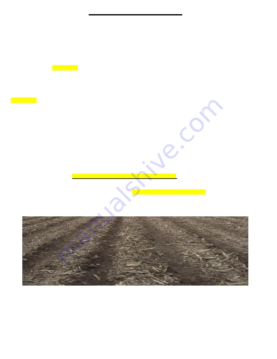
expect 100% of crop residue to be cleared, it is not necessary and would necessitate engaging the soil. The
width of path cleared depends on ground conditions, depth setting, and ground speed.
4.
DO
expect to see wheels occasionally quit turning, indicating ideal (shallow) setting which is not moving soil.
5.
DO
adjust toolbar frame he
ight 20”-22” and drawbar correctly. It is very important to ensure planter opener will follow
ground contours properly.
See Page 52 for the planter levelness and height
.
6.
DO NOT
run air pressure below 10psi or above 60psi. Full range of travel can be achieved between these settings.
7.
DO
grease the hub cavity of the bearings regularly. Even though the bearings are sealed, filling the hub keeps moisture,
dirt, & debris from entering the hub and ruining the seal.
See page 58 for greasing intervals.
8.
DO
NOT run the coulter, if equipped, deeper than the disc opener blades. Coulter should be set to run even or slightly
above disc opening blades depth.
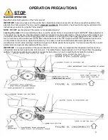
IMPORTANT:
For proper operation, the planter frame must operate level (fore, aft and side to side) and at the correct height,
typically 20”-22”. Regularly inspect the residue managers for loose or worn bolts & hardware. Repair or replace as needed.
Overview:
This electronic control system works with a pneumatic system that controls pressure in the air bags on an agricultural
application. The air bags provide independent up
AND
down pressure to the mechanical devices that are used on an
agricultural implement.
System Layout:
There are (3) main parts to the control system. First, a VDM (Valve Drive Module) is to provide Outputs to control functions of
the pneumatic system. The VDM will also provide Inputs to monitor the pneumatic system as well as provide feedback to the
operator. The second part is an in-cab display (Tablet or ISOBUS VT) that allows the operator to control the pneumatic system
and monitor its performance. Thirdly, the pneumatic system sends air to each circuit as commanded from the operator.
Содержание GERMINATE UNIFORMITY 2940
Страница 35: ...35 6 Row Airline Diagram 6 11 or 6 12 Split Row Airline Diagram...
Страница 36: ...36 8 Row Airline Diagram 8 15 8 16 Split Row Airline Diagram...
Страница 37: ...37 12 Row Airline Diagram...
Страница 39: ...39 16 Row Airline Diagram...
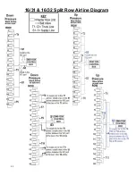
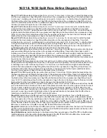
Страница 40: ...40 16 31 16 32 Split Row Airline Diagram...
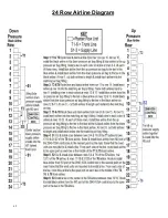
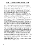
Страница 42: ...42 24 Row Airline Diagram...
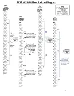
Страница 43: ...43 24 47 24 48 Row Airline Diagram...
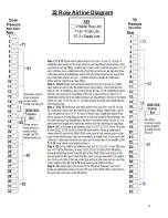
Страница 45: ...45 32 Row Airline Diagram...
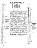
Страница 46: ...46 36 Row Airline Diagram...
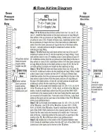
Страница 47: ...47 48 Row Airline Diagram...
Страница 48: ...48 54 Row Airline Diagram...
Страница 78: ...78 HYDRAULIC PUMP 2940 545 PARTS IDENTIFICATION PART REFERENCE ONLY...
Страница 82: ...82 2565 983_REV_B 09 21...


