22
Residue Manager(RM) Installation
Con’t
For Case Models Installing RM Only
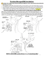
Step 1: 800
– 1200 SERIES:
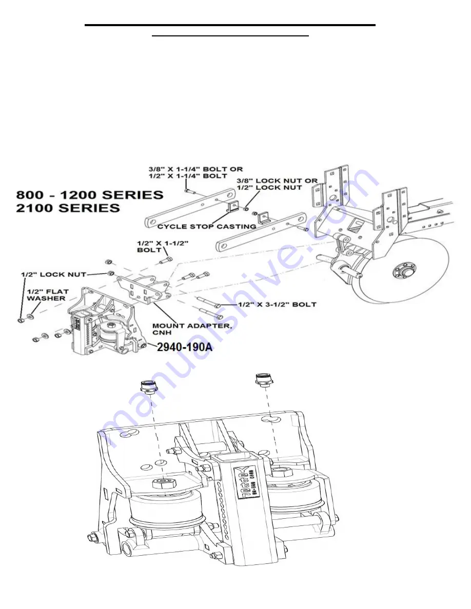
Place 1) Pneumatic RM Assembly (2940-190A), 1) CNH Adaptor Bracket (2940-209), 1) CNH
Mounting Bolt Bag (2940-145), 1) Wheel Mount (2940-215/2940-216), 1) Cyclo Stop Casting Bolt Bag (2965-135), 1) RH Wheel
Assembly (2966-140), 1) LH Wheel Assembly (2966-141), & 1) Wheel Mount Bolt Bag (2966-119), & 2) Bearing Shields (2967-
392) at each row unit. Mount 2940-190A to the 2940-
209 using 3) ½” X 1-1/2” GR5 bolts (note bolt direction), 3) ½” flat washers,
& 3) ½” lock nuts. Mount this assembly to row unit attachment casting using 2) ½” X 3-1/2” bolts & 2) ½” lock nuts. Install the 2)
Cyclo Stop casting pieces to each upper parallel arm using either A) 3/8 X 1-¼ bolts, 3/8 washer (not shown), & 3/8 lock nuts or
B) ½” X 1-1/4” bolts & ½” lock nuts. Note direction of mounting bolt. Cyclo stop castings can also be mounted to square hole on
the upstop flange under top parallel arms.
2100 SERIES:
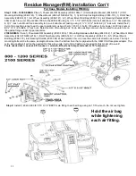
Place 1) Pneumatic RM Assembly (2940-190A), 1) Mounting Hardware Bolt Bag (2940-142), 1) Wheel Mount Weld
Assembly (2940-215/2940-216), 1) RH Wheel Assembly (2966-140), 1) LH Wheel Assembly (2966-141), & 1) Wheel Mount
Bolt Bag (2966-119), & 2) Bearing Shields (2967-392) at each planter row unit. Use the same bolt direction as below. The top 2
mounting bolts will be the same as diagram below. Use the bottom hole that is aligned with the OEM CNH faceplate adaptor. The
cylco stop casting kit will not be needed for these row units. Cyclo Stop Casting not needed for this model of row unit!
Tools needed are ¾ socket, 9/16 socket, ¾ wrench, 9/16 wrench, impact wrench
, & 10” extension
.
Step 2:
Install 1) 2940-380
3/8” PTC X 1/8” BSPP male fitting to each air bag using an 11/16 wrench. Do not over tighten.
Hold the air bag
while tightening
each air fitting.
Содержание GERMINATE UNIFORMITY 2940
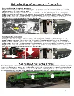
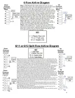
Страница 35: ...35 6 Row Airline Diagram 6 11 or 6 12 Split Row Airline Diagram...
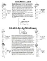
Страница 36: ...36 8 Row Airline Diagram 8 15 8 16 Split Row Airline Diagram...
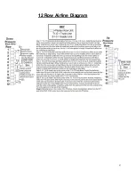
Страница 37: ...37 12 Row Airline Diagram...
Страница 39: ...39 16 Row Airline Diagram...
Страница 40: ...40 16 31 16 32 Split Row Airline Diagram...
Страница 42: ...42 24 Row Airline Diagram...
Страница 43: ...43 24 47 24 48 Row Airline Diagram...
Страница 45: ...45 32 Row Airline Diagram...
Страница 46: ...46 36 Row Airline Diagram...
Страница 47: ...47 48 Row Airline Diagram...
Страница 48: ...48 54 Row Airline Diagram...
Страница 78: ...78 HYDRAULIC PUMP 2940 545 PARTS IDENTIFICATION PART REFERENCE ONLY...
Страница 82: ...82 2565 983_REV_B 09 21...

