25
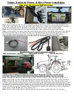
Tablet, Switched Power, & Main Power Installation
*Skip steps 1 & 2 if using ISOBUS monitor*
Step 1
: Begin installing the 2940-111 once an adequate mounting location has been found. Fix the base component of the
2940-111 Mounting Bracket in place to the back of the Tablet Holder using 4
– screws (A). Use items labeled B if mounting to a
slotted, flat mounting system & securely tighten the hardware. Use items C if using a tubular mounting system
Step 2:
Attach the Double Socket Arm to Tablet Holder & Ball Base, tighten clamp by turning the handle clockwise.
Step 3
:
Locate the 2940-153A cable & route bare ends into tractor cab, connector end should be at the tractor hitch. Install the
wire harness (not provided) for your tractor at the bare end of the 2940-153A & connect to tractors switched power source.
Secure the black ground wires together & the red wire on the 2940-153A to the orange wire on the OEM harness.
Cigarette outlet is NOT a switched port on all models of tractors, and therefore should not be used.
Switched
Power Source Connector part #’s:
JOHN DEERE PART #: RE67013 CNH PART #: 187103A1
CAT P/N: AG233356
FAILURE TO LINE UP TABS WHEN PLUGGING MALE INTO FEMALE CONNECTORS CAN RESULT IN SHORT CIRCUIT.
ALSO CHECK TAB & SLOT SIZES, PLUGGING CONNECTORS IN BACKWARDS WILL RESULT IN A FAULTY SYSTEM!!!
Step 4:
Install 2940-166 VDM power cable/40A breaker on battery, red cable to positive (+) stud, black cable to negative (-) stud.
Step 5:
Install the 2940-167 (10ft) or 2940-168 (20ft) VDM power extension cable to the 2940-166 & route to the hitch of the tractor.
Step 6:
Install the 2940-164A (5ft) or 2940-165A (10ft) PWR to Air Harness. This harness has 3 ends. Install the Anderson power
connector to power extension to battery from step 5, install 2 pin Duetsch to 2940-153A switched power harness from Step 3, & install
the male black 12 pin Deutsch connector to female end on the side of control box. If the control box is mounted further back than the
hitch of the planter, PWR to Air Extension harnesses need to be installed. Use 2940-170A (10ft), 2940-171A (30ft), & 2940-430A (20ft)
Extensions to reach to control box. On planters that fold, install PWR to Air extensions through draft tube or zip tie to outside frame. If
routing into the draft tube,
DO NOT
have a splice inside the draft.
Step 7:
Zip tie the cables and harnesses as needed keeping the install as neat as possible & harnesses out of harm’s way.
Содержание GERMINATE UNIFORMITY 2940
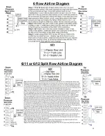
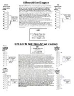
Страница 35: ...35 6 Row Airline Diagram 6 11 or 6 12 Split Row Airline Diagram...
Страница 36: ...36 8 Row Airline Diagram 8 15 8 16 Split Row Airline Diagram...
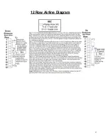
Страница 37: ...37 12 Row Airline Diagram...
Страница 39: ...39 16 Row Airline Diagram...
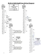
Страница 40: ...40 16 31 16 32 Split Row Airline Diagram...
Страница 42: ...42 24 Row Airline Diagram...
Страница 43: ...43 24 47 24 48 Row Airline Diagram...
Страница 45: ...45 32 Row Airline Diagram...
Страница 46: ...46 36 Row Airline Diagram...
Страница 47: ...47 48 Row Airline Diagram...
Страница 48: ...48 54 Row Airline Diagram...
Страница 78: ...78 HYDRAULIC PUMP 2940 545 PARTS IDENTIFICATION PART REFERENCE ONLY...
Страница 82: ...82 2565 983_REV_B 09 21...


