4 - 17
ENG
CARBURETOR
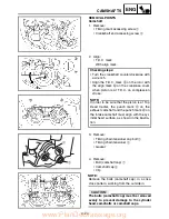
10. Install:
• Starter jet
1
• Pilot jet
2
• Spacer
3
• Needle jet
4
• Main jet
5
11. Install:
• Needle valve
1
• Float
2
• Float pin
3
NOTE:
• After installing the needle valve to the float,
install them to the carburetor.
• Check the float for smooth movement.
12. Install:
• Pilot screw
1
• Spring
2
• Washer
3
• O-ring
4
* Except for USA
Note the following installation points:
• Turn in the pilot screw until it is lightly
seated.
• Turn out the pilot screw by the number of
turns recorded before removing.
Pilot screw:
2 turns out (example)
* 1-7/8 turns out
13. Install:
• O-ring
• Leak jet
1
• Float chamber
2
• Screw (float chamber)
3
• Cable holder
(throttle stop screw cable)
4
• Hose holder
(carburetor breather hose)
5
www.PlanDeGraissage.org
Содержание WR250FR 2002
Страница 1: ...LIT 11626 16 48 WR250FR 5UM 28199 10 OWNER S SERVICE MANUAL www PlanDeGraissage org...
Страница 2: ...www PlanDeGraissage org...
Страница 5: ...www PlanDeGraissage org...
Страница 12: ...MEMO www PlanDeGraissage org...
Страница 118: ...3 53 INSP ADJ BATTERY INSPECTION AND CHARGING Charging method using a variable voltage charger www PlanDeGraissage org...
Страница 119: ...3 54 INSP ADJ BATTERY INSPECTION AND CHARGING Charging method using a constant voltage charger www PlanDeGraissage org...
Страница 143: ...4 21 ENG 9 Install Clamp 1 Refer to CABLE ROUTING DIAGRAM section in the CHAPTER 2 1 CARBURETOR www PlanDeGraissage org...


