background image

Manual 26518V2 

5009FT Installation/Hardware 


Woodward 

65 


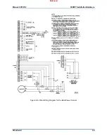
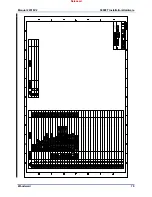
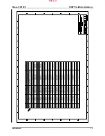
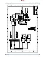
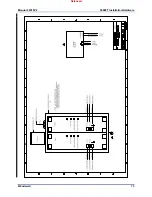
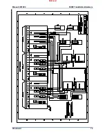
Figure 8-5. Real Power Sensor 


Released

Содержание MicroNet TMR 5009FT

Страница 1: ...518V2 Revision E 6 2018 Original Instructions MicroNet TMR 5009FT Fault Tolerant Steam Turbine Control Installation Hardware Manual Manual 26518 consists of 4 volumes 26518V1 26518V2 26518V3 26518V4 V...

Страница 2: ...o the equipment Any such unauthorized modifications i constitute misuse and or negligence within the meaning of the product warranty thereby excluding warranty coverage for any resulting damage and ii...

Страница 3: ...e 27 Actuator Outputs TMR Analog Combo Module 28 Actuator Outputs Actuator Controller Module 29 FTM Contact Inputs F T Relay Discrete In 33 FTM Relay Outputs F T Relay Outputs 34 Communications 41 Con...

Страница 4: ...gure 4 13 5009FT Compatible Position Feedback Schematics 30 Figure 4 12a Example of Single Loop with Dual Coil and Two LVDTs Type A B A B on Cylinder Valve 31 Figure 4 12b Example of Dual Loop with Du...

Страница 5: ...eed shutdown device to protect against runaway or damage to the prime mover with possible personal injury loss of life or property damage The overspeed shutdown device must be totally independent of t...

Страница 6: ...Protection of Electronic Controls Printed Circuit Boards and Modules Follow these precautions when working with or near the control 1 Avoid the build up of static electricity on your body by not wear...

Страница 7: ...device is considered permanently connect and requires a fixed wiring installation Protective Earth Grounding is required by the input PE terminals See Installation Chapter A disconnection device is no...

Страница 8: ...nnected from hazards live voltages before servicing This equipment is intended to be installed in a metal cabinet or enclosure See manual 26167 Volumes 1 2 for installation requirements related to CE...

Страница 9: ...ervice and Run Volume 4 provides details on installation and operation of the optional operator control station if provided with your system It contains a list of the control s Modbus registers and ta...

Страница 10: ...nts Designation Description Qty Remarks U1 Main chassis 1 Standard U2 Power Chassis 1 Standard PSM1 PSM2 Main Power Supply Module 2 Standard A1 Kernel Power Supply Module 3 Standard A2 CPU Module 3 St...

Страница 11: ...Power Supplies PSM1 and PSM2 The 5009FT main control power supply chassis uses redundant power supplies A motherboard located on the back of the power supply chassis allows the two power supplies to f...

Страница 12: ...mmunication peripherals These peripherals include 2 general use Ethernet ports 1 Real Time Network port 1 serial port 1 one service port and 2 CAN ports This module includes an FPGA to provide VMEbus...

Страница 13: ...age clamp terminal connection for customer field wiring Each FT Relay box contains circuitry for six contact inputs three relay outputs and houses circuitry to route each contact input signal to the s...

Страница 14: ...It is highly recommended to design the field wiring such that the latent fault detection can be utilized on critical relays Trips Without this feature a single component fault might not be annunciate...

Страница 15: ...Manual 26518V2 5009FT Installation Hardware Woodward 13 Figure 2 1 Fault Tolerant Relay Outline Drawing Released...

Страница 16: ...R 24 8 Analog module comes in the following configuration 24 channels of 4 20 mA inputs with 8 channels of 4 20 mA outputs 2 pole 10 ms filter on all input channels except channels 23 and 24 which hav...

Страница 17: ...e card The Pilot signal can be redundant if sent to card A106 and card B106 If physically only one LVDT signal is available the excitation can only be taken from one card but the signal can be put in...

Страница 18: ...t ratio 1000 1 View angle horizontal vertical CR 10 170 160 Installation cutout dimensions width x height 424 0 x 329 5 mm Outside bezel dimensions width x height x depth 452 0 x 356 5 x 10 mm Backlig...

Страница 19: ...er the following when selecting a location for mounting the 5009FT unit s Make sure the 5009FT unit s is mounted in a dry location protected from water and condensation Pollution Degree 2 environment...

Страница 20: ...provided at the terminal block for each of the speed sensor inputs actuator outputs analog inputs analog outputs and communications ports All of these inputs and outputs should be wired using shielde...

Страница 21: ...d Termination Diagram 1 Option 2 Analog signal shields grounded at device end The shields should be connected to earth ground at all intermediate terminal blocks as well as terminated at the control t...

Страница 22: ...ipped with input power switches Table 4 1 provides each power supply s holdup time specification which is the time the supply will continue to operate within specification after its input power is int...

Страница 23: ...se speed from the same gear The 5009FT control can sense and control turbine speed from a single speed probe however it is recommended that all applications use multiple speed probes to increase syste...

Страница 24: ...th either 12 Vdc or 24 Vdc open collector probes When interfacing to open collector type probes a pull up resistor between the four voltage terminal and the proximity return terminal is required Figur...

Страница 25: ...ernal pull up resistors are required when interfacing with an open collector type of proximity probe Proximity Probes only Jumpers must be installed from A B IN and to C IN as shown in Figure 4 5 to a...

Страница 26: ...d device which may have the potential of reaching over 200 Vdc with respect to the control s common the use of a loop isolator is recommended to break any return current paths which could result in er...

Страница 27: ...g input channel may power its own 4 20 mA transducer See Figure 4 8 for analog input connection This power is protected with a 100 mA fuse on each channel to prevent an inadvertent short from damaging...

Страница 28: ...pply outputs must be rated for 30 Vdc or less and have its outputs fused with appropriate sized fuses a maximum current rating of 100 V where V is the supply s rated voltage or 5 A whichever is less I...

Страница 29: ...program may annunciate the fault disable the channel and stop using data in system calculations or control Care should be taken to prevent ground loops and other faults when interfacing to non isolate...

Страница 30: ...ng Notes Refer to Figures 4 8 and 4 9 and Appendix A for Actuator Output wiring connections to the FTMs When configured to drive a single coil actuator user supplied jumpers are required between termi...

Страница 31: ...12b and Appendix A for Actuator Output FTM terminal assignments Figure 4 11 gives feedback schematics Maximum impedance for a 20 to 160 mA actuator output is 45 actuator impedance wire resistance Each...

Страница 32: ...Manual 26518V2 5009FT Installation Hardware Woodward 30 Figure 4 13 5009FT Compatible Position Feedback Schematics Released...

Страница 33: ...Manual 26518V2 5009FT Installation Hardware Woodward 31 Figure 4 12a Example of Single Loop with Dual Coil and Two LVDTs Type A B A B on Cylinder Valve Released...

Страница 34: ...Manual 26518V2 5009FT Installation Hardware Woodward 32 Figure 4 12b Example of Dual Loop with Dual Coil and Two LVDTs Type A B A B on Cylinder Valve and Two VDTs Type A B A B on Pilot Valve Released...

Страница 35: ...sense and register a change in state Contact wetting voltage can be supplied by the control or from an external source 24 Vdc contact wetting voltage is available on each FTM with isolation diodes on...

Страница 36: ...st have the desired switch condition or specific analog value assigned to them within the control s program Refer to Volume 3 of this manual for a complete list of programmable relay output options Th...

Страница 37: ...he load In most cases this has no bearing on the customer s circuitry because such a small amount of voltage is developed across its load However when a relay output is used with a very high resistanc...

Страница 38: ...7 5 Vac This voltage level is lower than the load s 25 Vac drop out voltage thus Latent Fault detection can be used with this example circuit If however the load resistance was 1200 the intersection...

Страница 39: ...6518V2 5009FT Installation Hardware Woodward 37 Figure 4 15 Latent Fault Detection Verification Graph 88 132 Vac Circuitry Figure 4 16 Latent Fault Detection Verification Graph 100 150 Vdc Circuitry R...

Страница 40: ...urce during system power up and power down This routine will guarantee that no relay is inadvertently energized due to system power up surges By using the FTM s internal relay coil power this start up...

Страница 41: ...Manual 26518V2 5009FT Installation Hardware Woodward 39 Figure 4 17 Jumper and Relay Location Diagram Released...

Страница 42: ...Coil Power Jumper bank is in the INT position If external relay coil power is supplied move the FTM s Relay Coil Power Jumper bank to the EXT position and verify that the external source is fully iso...

Страница 43: ...gurable to be used as a Modbus link Modbus 1 has three available slave communication links and Modbus 2 has two If both Ethernet ports 1 2 on same CPU s are to be used they must be configured with IP...

Страница 44: ...to Appendix A 2 Refer to MicroNet TMR manual 26167 for input power ratings 3 Consult the Customer supplied wiring 4 Optional Wiring dependent upon system options 5 Read and follow all Wiring notes in...

Страница 45: ...ard 43 Improperly calibrated devices can cause turbine damage and possible personnel injury or death Before starting the turbine for the first time and periodically thereafter verify the calibration o...

Страница 46: ...ither above or below the specified input range If this LED is on check the input voltage and correct the problem Long term operation with incorrect input voltages may permanently damage the power supp...

Страница 47: ...h kernel section of the MicroNet TMR control contains one kernel power supply module located in the first slot of the kernel This module receives 24 Vdc from the main TMR supply and regulates it to 5...

Страница 48: ...affect by the above procedure go to the Alarm Summary page and enter a RESET 10 All kernel and module alarms should clear restoring complete fault tolerance to the system Replacing a 5009FT CPU while...

Страница 49: ...s If this LED is on and remains on after a CPU reset replace the Kernel power supply FAULT LED This RED LED actively flashes CPU fault codes as necessary STANDBY LED NOT USED FOR TMR SYSTEMS I OLOCK L...

Страница 50: ...onnector on the motherboard make contact use even pressure exerted at the top and bottom of the Kernel Power Supply module s front panel 14 Tighten the two screws that secure the Kernel Power Supply m...

Страница 51: ...only difference is that the LVCC LED will be OFF the whole time Analog and Discrete I O Modules Kernel A B C A3 A5 Each I O Module has a red Fault LED controlled by the CPU that is turned on when the...

Страница 52: ...ent on the field connections and options connecting the wrong module part number to an FTM or FT Relay Module may cause a system shutdown 8 Install the replacement module by aligning the circuit board...

Страница 53: ...performed on line while the unit is operational or off line while the unit is shut down If on line replacement of the FTMs is required desired the user must consider this in the assignment of redundan...

Страница 54: ...ctors when replacing relays or cables If possible remove relay circuit power from all FTM relays before replacing any FTM relay or cable 1 Read all warnings at the beginning of this volume before repl...

Страница 55: ...ific Application 1 99 sysinit Problem in system initialization 184 185 186 VerifyCpuMem Problem in verify CPU memory 103 VerifyNVLog Problem in verify NV_LOG functions 104 143 145 ExecuteTMRMessageTas...

Страница 56: ...stroke be obtained and held Does the valve fully seat close before the governor reaches full minimum stroke Does the valve fully open before the governor reaches maximum stroke Is the bypass valve s i...

Страница 57: ...peed sensing pickup and the control correct Are there any grounding problems or worn shields Is the signal sufficient at least 1 5 Vrms Is the signal a clean sine wave or square wave with no spikes or...

Страница 58: ...ard 56 EXTERNAL DEVICES Are there external devices the control is dependent on for input signals Are these devices providing the correct signal to the control Is the external device configured or prog...

Страница 59: ...ations for Options EN 50178 Humidity Class EN 50178 Air Pressure Class 3K3 5 to 85 3K3 86 to 106 kPa Air Quality Pollution Degree 2 Altitude max 2000 m Storage Temperature 20 to 70 C 4 to 158 F Compon...

Страница 60: ...272 Vdc as on Power Supply Label Rated Maximum Current 3 0 A Input Power Fuse Breaker Rating 10 A slow blow Wire Size 2 5 mm 14 AWG or larger Holdup Time 7 ms 200 Vdc Installation Overvoltage Rating...

Страница 61: ...e way Fans Power must be removed prior to replacing chassis fans Only qualified personnel should replace chassis fans As a preventive maintenance it is recommended that the main chassis and power chas...

Страница 62: ...Woodward 60 Chapter 8 MicroNet TMR Compatible Products The following is a list of compatible Woodward products that may be used with the MicroNet TMR 5009FT System DSLC Panel Real Power Sensor Figure...

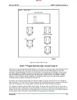
Страница 63: ...match voltages before paralleling It interfaces with the control via a speed bias signal to control generator frequency and phase see Figure 8 4 The DSLC along with its auxiliary devices will be moun...

Страница 64: ...are to leave sufficient space between the panel and walls objects etc for easy access 2 Drill and tap the mounting holes for appropriate size hardware see Figure 8 4 3 Place the panel in position inse...

Страница 65: ...Manual 26518V2 5009FT Installation Hardware Woodward 63 Figure 8 4 DSLC Control Released...

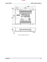
Страница 66: ...ring criteria before it is applied with the 5009 For more information on Woodward Real Power Sensors refer to Woodward manual 82018 Real Power Sensor Installation and Wiring Mount the Real Power Senso...

Страница 67: ...Manual 26518V2 5009FT Installation Hardware Woodward 65 Figure 8 5 Real Power Sensor Released...

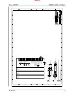
Страница 68: ...Manual 26518V2 5009FT Installation Hardware Woodward 66 Figure 8 6 Plant Wiring Diagram for the Real Power Sensor Released...

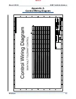
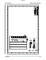
Страница 69: ...Manual 26518V2 5009FT Installation Hardware Woodward 67 Appendix A Control Wiring Diagram Released...

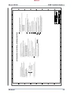
Страница 70: ...Manual 26518V2 5009FT Installation Hardware Woodward 68 Released...

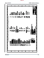
Страница 71: ...Manual 26518V2 5009FT Installation Hardware Woodward 69 Released...

Страница 72: ...Manual 26518V2 5009FT Installation Hardware Woodward 70 Released...

Страница 73: ...Manual 26518V2 5009FT Installation Hardware Woodward 71 Released...

Страница 74: ...Manual 26518V2 5009FT Installation Hardware Woodward 72 Released...

Страница 75: ...Manual 26518V2 5009FT Installation Hardware Woodward 73 Released...

Страница 76: ...Manual 26518V2 5009FT Installation Hardware Woodward 74 Released...

Страница 77: ...Manual 26518V2 5009FT Installation Hardware Woodward 75 Released...

Страница 78: ...Manual 26518V2 5009FT Installation Hardware Woodward 76 Released...

Страница 79: ...Manual 26518V2 5009FT Installation Hardware Woodward 77 Released...

Страница 80: ...Manual 26518V2 5009FT Installation Hardware Woodward 78 Released...

Страница 81: ...Manual 26518V2 5009FT Installation Hardware Woodward 79 Released...

Страница 82: ...Manual 26518V2 5009FT Installation Hardware Woodward 80 Released...

Страница 83: ...Manual 26518V2 5009FT Installation Hardware Woodward 81 Released...

Страница 84: ...Manual 26518V2 5009FT Installation Hardware Woodward 82 Released...

Страница 85: ...Manual 26518V2 5009FT Installation Hardware Woodward 83 Released...

Страница 86: ...Manual 26518V2 5009FT Installation Hardware Woodward 84 Released...

Страница 87: ...Manual 26518V2 5009FT Installation Hardware Woodward 85 Released...

Страница 88: ...Manual 26518V2 5009FT Installation Hardware Woodward 86 Released...

Страница 89: ...Manual 26518V2 5009FT Installation Hardware Woodward 87 Appendix B Standard Cabinet Layout Diagram Released...

Страница 90: ...Manual 26518V2 5009FT Installation Hardware Woodward 88 Released...

Страница 91: ...Manual 26518V2 5009FT Installation Hardware Woodward 89 Released...

Страница 92: ...Manual 26518V2 5009FT Installation Hardware Woodward 90 Released...

Страница 93: ...4679 Rev B Changes in Revision D Removed all references to Cabinet Removed Appendix A and renamed Appendix B to Appendix A Added new outline drawing to Appendix A Updated Declaration of Conformity Cha...

Страница 94: ...Manual 26518V2 5009FT Installation Hardware Woodward 92 Declarations Released...

Страница 95: ...0522 1519 USA 1041 Woodward Way Fort Collins CO 80524 USA Phone 1 970 482 5811 Email and Website www woodward com Woodward has company owned plants subsidiaries and branches as well as authorized dist...

Отзывы: