Manual 26518V2
5009FT Installation/Hardware
Woodward
64
Real Power Sensor (RPS)
The Real Power Sensor is used to sense the real power being produced by a generator, or flowing
through a tie line. Woodward Real Power Sensors sense three phase voltages and three phase currents.
The RPS compares each phase’s voltage to current relationship and develops a 4–20 mA output
proportional to real power.
The RPS provided with a standard 5009 system accepts only 0–5 A and has a kW and VAR readout. The
“KW Readout” terminals provide a 4–20 mA signal proportional to real power, which is used by, and
compatible with, the 5009 control.
Woodward-manufactured Real Power Sensors have a 2.5 Hz low pass filter (400 ms lag time) on the
output to filter out the high frequency noise typically created in a switchgear-type environment. If another
vendor’s watt transducer is used, verify that it has similar filtering criteria before it is applied with the 5009.
For more information on Woodward Real Power Sensors, refer to Woodward manual 82018.
Real Power Sensor Installation and Wiring
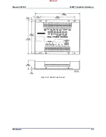
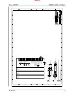
Mount the Real Power Sensor using the four mounting holes provided on the flanges of the enclosure
(see Figure 8-5).
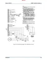
Connect external wiring to the Real Power Sensor as shown in Figure 8-6. When making wire
connections, observe the following wiring recommendations:
Use 0.5 mm² (20 AWG) or larger stranded, twisted shielded wire for all signal-carrying wires.
Use 0.8 mm² (18 AWG) or larger stranded wire for all potential and current transformer connections.
Ensure all wires shown in Figure 8-5 as shielded are actually shielded wires.
Do not place shielded wires in cable conduits with high-voltage or high-current carrying cables.
Do not connect the cable shields to any external grounds. The cable shield is grounded at the power
sensor end only.
Make sure that cable shields are connected through all intermediate terminal blocks from the signal
source to the signal termination. (Do not leave any floating grounds.)
Released
Содержание MicroNet TMR 5009FT
Страница 41: ...Manual 26518V2 5009FT Installation Hardware Woodward 39 Figure 4 17 Jumper and Relay Location Diagram Released...
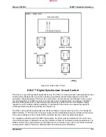
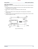
Страница 65: ...Manual 26518V2 5009FT Installation Hardware Woodward 63 Figure 8 4 DSLC Control Released...
Страница 67: ...Manual 26518V2 5009FT Installation Hardware Woodward 65 Figure 8 5 Real Power Sensor Released...
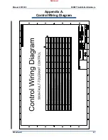
Страница 69: ...Manual 26518V2 5009FT Installation Hardware Woodward 67 Appendix A Control Wiring Diagram Released...
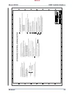
Страница 70: ...Manual 26518V2 5009FT Installation Hardware Woodward 68 Released...
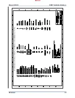
Страница 71: ...Manual 26518V2 5009FT Installation Hardware Woodward 69 Released...
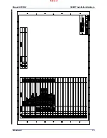
Страница 72: ...Manual 26518V2 5009FT Installation Hardware Woodward 70 Released...
Страница 73: ...Manual 26518V2 5009FT Installation Hardware Woodward 71 Released...
Страница 74: ...Manual 26518V2 5009FT Installation Hardware Woodward 72 Released...
Страница 75: ...Manual 26518V2 5009FT Installation Hardware Woodward 73 Released...
Страница 76: ...Manual 26518V2 5009FT Installation Hardware Woodward 74 Released...
Страница 77: ...Manual 26518V2 5009FT Installation Hardware Woodward 75 Released...
Страница 78: ...Manual 26518V2 5009FT Installation Hardware Woodward 76 Released...
Страница 79: ...Manual 26518V2 5009FT Installation Hardware Woodward 77 Released...
Страница 80: ...Manual 26518V2 5009FT Installation Hardware Woodward 78 Released...
Страница 81: ...Manual 26518V2 5009FT Installation Hardware Woodward 79 Released...
Страница 82: ...Manual 26518V2 5009FT Installation Hardware Woodward 80 Released...
Страница 83: ...Manual 26518V2 5009FT Installation Hardware Woodward 81 Released...
Страница 84: ...Manual 26518V2 5009FT Installation Hardware Woodward 82 Released...
Страница 85: ...Manual 26518V2 5009FT Installation Hardware Woodward 83 Released...
Страница 86: ...Manual 26518V2 5009FT Installation Hardware Woodward 84 Released...
Страница 87: ...Manual 26518V2 5009FT Installation Hardware Woodward 85 Released...
Страница 88: ...Manual 26518V2 5009FT Installation Hardware Woodward 86 Released...
Страница 89: ...Manual 26518V2 5009FT Installation Hardware Woodward 87 Appendix B Standard Cabinet Layout Diagram Released...
Страница 90: ...Manual 26518V2 5009FT Installation Hardware Woodward 88 Released...
Страница 91: ...Manual 26518V2 5009FT Installation Hardware Woodward 89 Released...
Страница 92: ...Manual 26518V2 5009FT Installation Hardware Woodward 90 Released...
Страница 94: ...Manual 26518V2 5009FT Installation Hardware Woodward 92 Declarations Released...


