Manual 26518V2
5009FT Installation/Hardware
Woodward
24
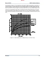
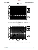
Figure 4-7. MPU Pickup Voltage vs Frequency
Analog Inputs—TMR Analog Combo Module
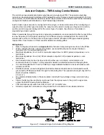
The base offering control accepts eight 4–20 mA current inputs, with each of the control’s two FTMs
accepting four inputs. All analog inputs may be used with two-wire ungrounded (loop powered)
transducers or isolated (self-powered) transducers. Because inputs are not fully isolated, care must be
taken in their application and maintenance to avoid “ground-loop” type problems. All analog inputs have
200 Vdc common mode rejection isolation. If interfacing to a non-isolated device which may have the
potential of reaching over 200 Vdc with respect to the control’s common, the use of a loop isolator is
recommended to break any return current paths, which could result in erroneous readings.
All eight analog inputs are programmable. When an analog input is used, the chosen input must be wired
to and configured within the control’s program to function. Refer to Volume 3 of this manual for a
complete list of programmable analog input options.
A 24 Vdc power supply is available from the 5009FT control to power external transducers or other
auxiliary devices. Isolation is provided through diodes on the power and common lines. This 24 Vdc
output is capable of providing 24 Vdc with +10% regulation. Power connections are be made through
terminals located on system FTMs.
Released
Содержание MicroNet TMR 5009FT
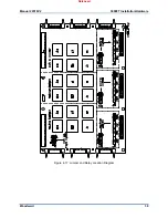
Страница 41: ...Manual 26518V2 5009FT Installation Hardware Woodward 39 Figure 4 17 Jumper and Relay Location Diagram Released...
Страница 65: ...Manual 26518V2 5009FT Installation Hardware Woodward 63 Figure 8 4 DSLC Control Released...
Страница 67: ...Manual 26518V2 5009FT Installation Hardware Woodward 65 Figure 8 5 Real Power Sensor Released...
Страница 69: ...Manual 26518V2 5009FT Installation Hardware Woodward 67 Appendix A Control Wiring Diagram Released...
Страница 70: ...Manual 26518V2 5009FT Installation Hardware Woodward 68 Released...
Страница 71: ...Manual 26518V2 5009FT Installation Hardware Woodward 69 Released...
Страница 72: ...Manual 26518V2 5009FT Installation Hardware Woodward 70 Released...
Страница 73: ...Manual 26518V2 5009FT Installation Hardware Woodward 71 Released...
Страница 74: ...Manual 26518V2 5009FT Installation Hardware Woodward 72 Released...
Страница 75: ...Manual 26518V2 5009FT Installation Hardware Woodward 73 Released...
Страница 76: ...Manual 26518V2 5009FT Installation Hardware Woodward 74 Released...
Страница 77: ...Manual 26518V2 5009FT Installation Hardware Woodward 75 Released...
Страница 78: ...Manual 26518V2 5009FT Installation Hardware Woodward 76 Released...
Страница 79: ...Manual 26518V2 5009FT Installation Hardware Woodward 77 Released...
Страница 80: ...Manual 26518V2 5009FT Installation Hardware Woodward 78 Released...
Страница 81: ...Manual 26518V2 5009FT Installation Hardware Woodward 79 Released...
Страница 82: ...Manual 26518V2 5009FT Installation Hardware Woodward 80 Released...
Страница 83: ...Manual 26518V2 5009FT Installation Hardware Woodward 81 Released...
Страница 84: ...Manual 26518V2 5009FT Installation Hardware Woodward 82 Released...
Страница 85: ...Manual 26518V2 5009FT Installation Hardware Woodward 83 Released...
Страница 86: ...Manual 26518V2 5009FT Installation Hardware Woodward 84 Released...
Страница 87: ...Manual 26518V2 5009FT Installation Hardware Woodward 85 Released...
Страница 88: ...Manual 26518V2 5009FT Installation Hardware Woodward 86 Released...
Страница 89: ...Manual 26518V2 5009FT Installation Hardware Woodward 87 Appendix B Standard Cabinet Layout Diagram Released...
Страница 90: ...Manual 26518V2 5009FT Installation Hardware Woodward 88 Released...
Страница 91: ...Manual 26518V2 5009FT Installation Hardware Woodward 89 Released...
Страница 92: ...Manual 26518V2 5009FT Installation Hardware Woodward 90 Released...
Страница 94: ...Manual 26518V2 5009FT Installation Hardware Woodward 92 Declarations Released...

