Manual 26518V2
5009FT Installation/Hardware
Woodward
55
COMMUNICATIONS
Are the LAN switches powered and operable?
Are the Ethernet (or Serial) cables all securely connected at both ends?
Are the IP addresses on the same network domain (within subnet mask)?
Are any IP addresses duplicated? (LAN will prevent second one from joining)
Is the 5009FT configured correctly for desired port/protocol/slave #?
Are there status LEDs that can be checked for activity (on Ethernet)?
INPUT SIGNALS
Are all input signals properly scaled?
Are the inputs free of electrical noise and properly shielded?
Is the wiring correct?
Have all field input signals to the control been verified?
Is the polarity of the signals correct?
OUTPUT SIGNALS
Are the outputs calibrated?
Have the actuator drivers been calibrated to the stroke of the turbine valves?
Are the output signals free of noise and properly shielded?
Is the wiring correct?
TRANSDUCERS
Is the transducer calibrated for the proper range?
Has it been tested by simulating its input and measuring its output signal?
Does the transducer have power?
Are the sensing lines feeding the transducer clear of obstructions?
MAGNETIC PICKUPS AND OTHER SPEED SENSING DEVICES
Is the wiring between the speed sensing pickup and the control correct?
Are there any grounding problems or worn shields?
Is the signal sufficient (at least 1.5 Vrms)?
Is the signal a clean sine wave or square wave with no spikes or distortions?
Is the MPU head clean and free of oil or metallic particles?
Is the MPU head free of any nicks or chips?
Is the MPU or proximity probe correctly aligned with the gear?
Is the speed sensing probe adjusted to the correct gap?
Is the speed sensing probe head the correct size for the toothed wheel it is being used with?
Are the proper jumpers installed on the FTM?
INPUT VOLTAGE/POWER SUPPLIES
Is the input power within the range of the control’s power supply input?
Is the input power free of switching noise or transient spikes?
Is the power circuit dedicated to the governor only?
Are the control’s supplies indicating that they are OK?
Are the control’s supplies outputting the correct voltage?
ELECTRICAL CONNECTIONS
Are all electrical connections tight and clean?
Are all signal wires shielded?
Are shields continuous from the device to the control?
Are the shields terminated according to Woodward specifications?
Are there low voltage signal wires running in the same wiring trays as high voltage wiring?
Are the governor’s signal common or grounds not tied to any other devices?
Have the signals been checked for electrical noise?
VOLTAGE REGULATOR
Is the voltage regulator working properly?
Released
Содержание MicroNet TMR 5009FT
Страница 41: ...Manual 26518V2 5009FT Installation Hardware Woodward 39 Figure 4 17 Jumper and Relay Location Diagram Released...
Страница 65: ...Manual 26518V2 5009FT Installation Hardware Woodward 63 Figure 8 4 DSLC Control Released...
Страница 67: ...Manual 26518V2 5009FT Installation Hardware Woodward 65 Figure 8 5 Real Power Sensor Released...
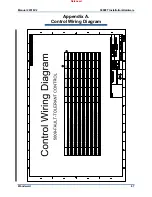
Страница 69: ...Manual 26518V2 5009FT Installation Hardware Woodward 67 Appendix A Control Wiring Diagram Released...
Страница 70: ...Manual 26518V2 5009FT Installation Hardware Woodward 68 Released...
Страница 71: ...Manual 26518V2 5009FT Installation Hardware Woodward 69 Released...
Страница 72: ...Manual 26518V2 5009FT Installation Hardware Woodward 70 Released...
Страница 73: ...Manual 26518V2 5009FT Installation Hardware Woodward 71 Released...
Страница 74: ...Manual 26518V2 5009FT Installation Hardware Woodward 72 Released...
Страница 75: ...Manual 26518V2 5009FT Installation Hardware Woodward 73 Released...
Страница 76: ...Manual 26518V2 5009FT Installation Hardware Woodward 74 Released...
Страница 77: ...Manual 26518V2 5009FT Installation Hardware Woodward 75 Released...
Страница 78: ...Manual 26518V2 5009FT Installation Hardware Woodward 76 Released...
Страница 79: ...Manual 26518V2 5009FT Installation Hardware Woodward 77 Released...
Страница 80: ...Manual 26518V2 5009FT Installation Hardware Woodward 78 Released...
Страница 81: ...Manual 26518V2 5009FT Installation Hardware Woodward 79 Released...
Страница 82: ...Manual 26518V2 5009FT Installation Hardware Woodward 80 Released...
Страница 83: ...Manual 26518V2 5009FT Installation Hardware Woodward 81 Released...
Страница 84: ...Manual 26518V2 5009FT Installation Hardware Woodward 82 Released...
Страница 85: ...Manual 26518V2 5009FT Installation Hardware Woodward 83 Released...
Страница 86: ...Manual 26518V2 5009FT Installation Hardware Woodward 84 Released...
Страница 87: ...Manual 26518V2 5009FT Installation Hardware Woodward 85 Released...
Страница 88: ...Manual 26518V2 5009FT Installation Hardware Woodward 86 Released...
Страница 89: ...Manual 26518V2 5009FT Installation Hardware Woodward 87 Appendix B Standard Cabinet Layout Diagram Released...
Страница 90: ...Manual 26518V2 5009FT Installation Hardware Woodward 88 Released...
Страница 91: ...Manual 26518V2 5009FT Installation Hardware Woodward 89 Released...
Страница 92: ...Manual 26518V2 5009FT Installation Hardware Woodward 90 Released...
Страница 94: ...Manual 26518V2 5009FT Installation Hardware Woodward 92 Declarations Released...

