Manual 26518V2
5009FT Installation/Hardware
Woodward
18
Chapter 4.
Electrical Installation
Introduction
Before installation read all information and warnings on pages iv and
v of this volume.
Electrical ratings, wiring requirements, and options are provided to allow a customer to fully install the
5009FT control into a new or existing application. Field wiring must be rated at least 25 °C above ambient
temperature.
Wiring for installations must be in accordance with Ordinary (non-hazardous) wiring methods and in
accordance with the authority having jurisdiction.
After the system has been mechanically installed read this chapter thoroughly before proceeding. Perform
system electrical installation by stepping through this chapter’s instructions in sequence. Start with system
cables instruction, then step to the next set of instructions, etc.
The installer should create a 5009FT I/O configuration wiring list to assist in electrical installation
(see Volume 3). The wiring list will determine what inputs are hooked up to what terminal blocks
and how the accessories are wired into the control.
Shields and Grounding
An individual shield termination is provided at the terminal block for each of the speed sensor inputs,
actuator outputs, analog inputs, analog outputs, and communications ports. All of these inputs and
outputs should be wired using shielded, twisted-pair wiring. See options below for correct shield
terminations for your installation. The exposed wire length, beyond the shield, should be limited to one
inch. Relay outputs, contact inputs, and power supply wiring do not normally require shielding, but can be
shielded if desired.
For compliance with EMC standards, it is required that all analog and discrete input/output wiring be
separated from all power wiring. It is also required to follow shielding and grounding practices as called
out in the manual 26167 Volume 1 & Volume 2.
Signal Wiring—
OPTION 1 (Typical to most industrial sites)—
Analog signal shields floating at device end and hard
grounded at Control end.
Ensure the FTM Ground Terminals are grounded to Earth (terminal 52 on
FTM103-1, -2 and terminal 37 on FTM106-1, -2).
In this case, the device shield needs to be grounded at the Woodward FTMs. Grounding bars are
installed in the FTMs to support this configuration since it is the most common. If the device shields are
grounded (to Chassis ground) at the device end, then REMOVE these shorting bars and follow option two
OR
the individual tabs from the Grounding bar can be cut off.
Released
Содержание MicroNet TMR 5009FT
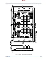
Страница 41: ...Manual 26518V2 5009FT Installation Hardware Woodward 39 Figure 4 17 Jumper and Relay Location Diagram Released...
Страница 65: ...Manual 26518V2 5009FT Installation Hardware Woodward 63 Figure 8 4 DSLC Control Released...
Страница 67: ...Manual 26518V2 5009FT Installation Hardware Woodward 65 Figure 8 5 Real Power Sensor Released...
Страница 69: ...Manual 26518V2 5009FT Installation Hardware Woodward 67 Appendix A Control Wiring Diagram Released...
Страница 70: ...Manual 26518V2 5009FT Installation Hardware Woodward 68 Released...
Страница 71: ...Manual 26518V2 5009FT Installation Hardware Woodward 69 Released...
Страница 72: ...Manual 26518V2 5009FT Installation Hardware Woodward 70 Released...
Страница 73: ...Manual 26518V2 5009FT Installation Hardware Woodward 71 Released...
Страница 74: ...Manual 26518V2 5009FT Installation Hardware Woodward 72 Released...
Страница 75: ...Manual 26518V2 5009FT Installation Hardware Woodward 73 Released...
Страница 76: ...Manual 26518V2 5009FT Installation Hardware Woodward 74 Released...
Страница 77: ...Manual 26518V2 5009FT Installation Hardware Woodward 75 Released...
Страница 78: ...Manual 26518V2 5009FT Installation Hardware Woodward 76 Released...
Страница 79: ...Manual 26518V2 5009FT Installation Hardware Woodward 77 Released...
Страница 80: ...Manual 26518V2 5009FT Installation Hardware Woodward 78 Released...
Страница 81: ...Manual 26518V2 5009FT Installation Hardware Woodward 79 Released...
Страница 82: ...Manual 26518V2 5009FT Installation Hardware Woodward 80 Released...
Страница 83: ...Manual 26518V2 5009FT Installation Hardware Woodward 81 Released...
Страница 84: ...Manual 26518V2 5009FT Installation Hardware Woodward 82 Released...
Страница 85: ...Manual 26518V2 5009FT Installation Hardware Woodward 83 Released...
Страница 86: ...Manual 26518V2 5009FT Installation Hardware Woodward 84 Released...
Страница 87: ...Manual 26518V2 5009FT Installation Hardware Woodward 85 Released...
Страница 88: ...Manual 26518V2 5009FT Installation Hardware Woodward 86 Released...
Страница 89: ...Manual 26518V2 5009FT Installation Hardware Woodward 87 Appendix B Standard Cabinet Layout Diagram Released...
Страница 90: ...Manual 26518V2 5009FT Installation Hardware Woodward 88 Released...
Страница 91: ...Manual 26518V2 5009FT Installation Hardware Woodward 89 Released...
Страница 92: ...Manual 26518V2 5009FT Installation Hardware Woodward 90 Released...
Страница 94: ...Manual 26518V2 5009FT Installation Hardware Woodward 92 Declarations Released...

