Manual 26518V2
5009FT Installation/Hardware
Woodward
41
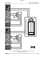
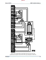
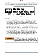
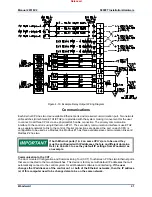
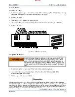
Figure 4-19. Example Relay Output Wiring Diagram
Communications
Each Kernel CPU has two User-available Ethernet ports and one serial communication port. Two network
LAN switches (Hirschmann ETH1/ETH2) are provided with the system making it convenient for the user
to connect to all three CPU’s via one physical RJ45 cable connection. The primary communication
interface to the control is using Ethernet on ETH1. The secondary communication interface is use ETH2
as a separate network to link to the control. If serial connections are desired, the port on each CPU is
configurable to be used as a Modbus link. Modbus #1 has three available slave communication links and
Modbus #2 has two.
If both Ethernet ports (1 & 2 on same CPU’s) are to be used they
must be configured with IP addresses that are on different domains.
Refer to Volume 3 to see they default IP settings from Woodward as
an example.
Communication to the CCT –
The door mounted Configuration and Commissioning Tool (CCT) Touchscreen PC has two Ethernet ports
that are connected to the two LAN switches. This device is factory set with default IP addresses that will
automatically connect to the control system for all Woodward software tool interfacing.
If the user
changes the IP addresses of the control on 1 or both of the Ethernet networks, then the IP address
(s) of this computer need to be changed also to be on the same network.
Released
Содержание MicroNet TMR 5009FT
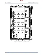
Страница 41: ...Manual 26518V2 5009FT Installation Hardware Woodward 39 Figure 4 17 Jumper and Relay Location Diagram Released...
Страница 65: ...Manual 26518V2 5009FT Installation Hardware Woodward 63 Figure 8 4 DSLC Control Released...
Страница 67: ...Manual 26518V2 5009FT Installation Hardware Woodward 65 Figure 8 5 Real Power Sensor Released...
Страница 69: ...Manual 26518V2 5009FT Installation Hardware Woodward 67 Appendix A Control Wiring Diagram Released...
Страница 70: ...Manual 26518V2 5009FT Installation Hardware Woodward 68 Released...
Страница 71: ...Manual 26518V2 5009FT Installation Hardware Woodward 69 Released...
Страница 72: ...Manual 26518V2 5009FT Installation Hardware Woodward 70 Released...
Страница 73: ...Manual 26518V2 5009FT Installation Hardware Woodward 71 Released...
Страница 74: ...Manual 26518V2 5009FT Installation Hardware Woodward 72 Released...
Страница 75: ...Manual 26518V2 5009FT Installation Hardware Woodward 73 Released...
Страница 76: ...Manual 26518V2 5009FT Installation Hardware Woodward 74 Released...
Страница 77: ...Manual 26518V2 5009FT Installation Hardware Woodward 75 Released...
Страница 78: ...Manual 26518V2 5009FT Installation Hardware Woodward 76 Released...
Страница 79: ...Manual 26518V2 5009FT Installation Hardware Woodward 77 Released...
Страница 80: ...Manual 26518V2 5009FT Installation Hardware Woodward 78 Released...
Страница 81: ...Manual 26518V2 5009FT Installation Hardware Woodward 79 Released...
Страница 82: ...Manual 26518V2 5009FT Installation Hardware Woodward 80 Released...
Страница 83: ...Manual 26518V2 5009FT Installation Hardware Woodward 81 Released...
Страница 84: ...Manual 26518V2 5009FT Installation Hardware Woodward 82 Released...
Страница 85: ...Manual 26518V2 5009FT Installation Hardware Woodward 83 Released...
Страница 86: ...Manual 26518V2 5009FT Installation Hardware Woodward 84 Released...
Страница 87: ...Manual 26518V2 5009FT Installation Hardware Woodward 85 Released...
Страница 88: ...Manual 26518V2 5009FT Installation Hardware Woodward 86 Released...
Страница 89: ...Manual 26518V2 5009FT Installation Hardware Woodward 87 Appendix B Standard Cabinet Layout Diagram Released...
Страница 90: ...Manual 26518V2 5009FT Installation Hardware Woodward 88 Released...
Страница 91: ...Manual 26518V2 5009FT Installation Hardware Woodward 89 Released...
Страница 92: ...Manual 26518V2 5009FT Installation Hardware Woodward 90 Released...
Страница 94: ...Manual 26518V2 5009FT Installation Hardware Woodward 92 Declarations Released...


