Manual 26518V2
5009FT Installation/Hardware
Woodward
23
Each FTM connects to the control’s MPU & Analog I/O modules through individual cables, and provides a
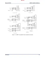
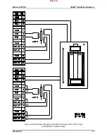
common cage-clamp terminal connection for customer field wiring. Figures 4-4 and 4-5 illustrate the
different input wiring configurations based on the type of speed sensing probes used.
Wiring Notes:
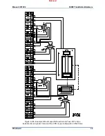
Refer to Figures 4-2, 4-3, and
Appendix A
for Speed Sensor wiring connections on the FTMs.
Each Speed input channel can only accept one MPU or one Proximity probe at a time.
If only 2 inputs are available they can be configured and connected as channel 1 and channel 3 (skip
#2) which will place inputs on different FTM modules.
MPUs only (ch1-3)—Jumper must be added to each channel as shown in Figure 4-4 to allow the “C”
analog module to sense speed.
MPUs only (ch1-3)—Jumper must be installed from ‘PROXRTN’ to ‘COM PROX’ as shown in Figure
4-4 to avoid noise issues.
Proximity Probes only—Individual 12 Vdc and 24 Vdc sources, with isolation diodes on the power,
common, and output source lines, are provided with each speed input to power system proximity
probes (100 mA fuses are used on the 24 V output, the 12 V is current limited to 100 mA and located
on the FTMs).
Proximity Probes only—External pull-up resistors are required when interfacing with an open
collector type of proximity probe.
Proximity Probes only—Jumpers must be installed from ‘A&B IN’ and to ‘C IN’ as shown in Figure 4-
5 to avoid noise issues.
Proximity Probes only—If using external power for these inputs, the power supply should be isolated
and must be located within 30 m of the MTMR chassis.
It is required that twisted shielded wiring be used between each probe and FTM.
Shields should be connected together at all intermediate terminal blocks and terminated to earth
ground at the FTM terminal block through the Grounding Bar. The exposed wire length, beyond the
shield, should be limited to 25 mm (1”).
FTM terminals accept wires from 0.08–2.5 mm² (27–12 AWG).
The installation of jumpers on the unused terminals listed in the
above wiring notes are extremely important to ensure that the control
receives good clean speed frequency inputs.
If the speed signals are not within the following limits, the 5009FT
control will respond with a speed sensor frequency error during the
program checking procedure.
(TxMxR)/60 must be < 25 000 Hz
T = Gear Teeth
M = (Overspeed Test Limit Setting x 1.02)
R = Gear Ratio
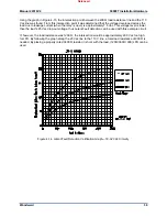
If the MPU device is not providing a voltage greater than 1.5 Vrms,
the MPU device should be moved closer to the gear where speed is
being monitored. The following graph shows the minimum voltage
necessary to detect speed at the various frequencies.
Released
Содержание MicroNet TMR 5009FT
Страница 41: ...Manual 26518V2 5009FT Installation Hardware Woodward 39 Figure 4 17 Jumper and Relay Location Diagram Released...
Страница 65: ...Manual 26518V2 5009FT Installation Hardware Woodward 63 Figure 8 4 DSLC Control Released...
Страница 67: ...Manual 26518V2 5009FT Installation Hardware Woodward 65 Figure 8 5 Real Power Sensor Released...
Страница 69: ...Manual 26518V2 5009FT Installation Hardware Woodward 67 Appendix A Control Wiring Diagram Released...
Страница 70: ...Manual 26518V2 5009FT Installation Hardware Woodward 68 Released...
Страница 71: ...Manual 26518V2 5009FT Installation Hardware Woodward 69 Released...
Страница 72: ...Manual 26518V2 5009FT Installation Hardware Woodward 70 Released...
Страница 73: ...Manual 26518V2 5009FT Installation Hardware Woodward 71 Released...
Страница 74: ...Manual 26518V2 5009FT Installation Hardware Woodward 72 Released...
Страница 75: ...Manual 26518V2 5009FT Installation Hardware Woodward 73 Released...
Страница 76: ...Manual 26518V2 5009FT Installation Hardware Woodward 74 Released...
Страница 77: ...Manual 26518V2 5009FT Installation Hardware Woodward 75 Released...
Страница 78: ...Manual 26518V2 5009FT Installation Hardware Woodward 76 Released...
Страница 79: ...Manual 26518V2 5009FT Installation Hardware Woodward 77 Released...
Страница 80: ...Manual 26518V2 5009FT Installation Hardware Woodward 78 Released...
Страница 81: ...Manual 26518V2 5009FT Installation Hardware Woodward 79 Released...
Страница 82: ...Manual 26518V2 5009FT Installation Hardware Woodward 80 Released...
Страница 83: ...Manual 26518V2 5009FT Installation Hardware Woodward 81 Released...
Страница 84: ...Manual 26518V2 5009FT Installation Hardware Woodward 82 Released...
Страница 85: ...Manual 26518V2 5009FT Installation Hardware Woodward 83 Released...
Страница 86: ...Manual 26518V2 5009FT Installation Hardware Woodward 84 Released...
Страница 87: ...Manual 26518V2 5009FT Installation Hardware Woodward 85 Released...
Страница 88: ...Manual 26518V2 5009FT Installation Hardware Woodward 86 Released...
Страница 89: ...Manual 26518V2 5009FT Installation Hardware Woodward 87 Appendix B Standard Cabinet Layout Diagram Released...
Страница 90: ...Manual 26518V2 5009FT Installation Hardware Woodward 88 Released...
Страница 91: ...Manual 26518V2 5009FT Installation Hardware Woodward 89 Released...
Страница 92: ...Manual 26518V2 5009FT Installation Hardware Woodward 90 Released...
Страница 94: ...Manual 26518V2 5009FT Installation Hardware Woodward 92 Declarations Released...

