Manual 26518V2
5009FT Installation/Hardware
Woodward
51
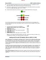
If the module’s Fault LED does not turn off after the module has been
installed for at least one minute, it may be necessary to re-seat the
module more firmly. To re-seat a module follow step #3 of the above
procedure to release the module from the motherboard, then re-
install the module by following procedure steps #8 and #9.
2 Channel Actuator Module (Kernel A/B: A6)
Analog Module and FTM troubleshooting instructions apply to the 2 Channel Actuator Module and FTM
with the exception of the fuses. The Actuator FTM does not contain any fuses, however the Actuator
Controller Module does have a fuse accessible at the rear bottom edge of the module. In case of module
non-operation, this fuse may be checked before replacing the module. If it is faulty replace with a .2 A /
250 V fuse.
Attention to wiring details must be followed when installing and commissioning the valve/actuators used
at a specific site to ensure that on-line replaceability of the actuator module can be done. Ensure that all
redundant signals are connected to only one of the actuator FTMs.
Termination Modules
The replacement of termination modules can be performed on-line (while the unit is operational) or off-line
(while the unit is shut down).
If on-line replacement of the FTMs is required/desired, the user must
consider this in the assignment of redundant input signals. For
example, use speed signals 1 & 3 (not 1 &2) and place redundant AI
signals on channels 1 & 5 (not 1 & 2).
Caution must be taken whenever replacing a termination module on-line, or a unit trip could result. The
procedure used in the replacement of termination modules on-line varies based on the control’s
configuration and system wiring configuration. Contact a Woodward representative to establish the
correct termination procedure to use based on your configuration.
To replace an Analog or Discrete Termination Module while the unit is off-line:
1. Read all warnings at the beginning of this Volume before replacing any module.
2. Shut down the control.
3. Remove all power from the system. Do not attempt to replace a termination module with the system
powered.
4. Disconnect all FTM and field wiring.
5. Disconnect all FTM cables. The I/O cables use a slide latch (to disengage, slide the latch toward the
cable end).
6. Remove the termination module from its panel and install its replacement.
7. Re-connect all cables. The I/O cables use a slide latch; to secure cable, slide the latch away from the
cable end.
8. Re-connect all field wiring.
9. Re-apply all power to the system.
Released
Содержание MicroNet TMR 5009FT
Страница 41: ...Manual 26518V2 5009FT Installation Hardware Woodward 39 Figure 4 17 Jumper and Relay Location Diagram Released...
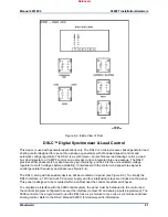
Страница 65: ...Manual 26518V2 5009FT Installation Hardware Woodward 63 Figure 8 4 DSLC Control Released...
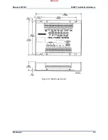
Страница 67: ...Manual 26518V2 5009FT Installation Hardware Woodward 65 Figure 8 5 Real Power Sensor Released...
Страница 69: ...Manual 26518V2 5009FT Installation Hardware Woodward 67 Appendix A Control Wiring Diagram Released...
Страница 70: ...Manual 26518V2 5009FT Installation Hardware Woodward 68 Released...
Страница 71: ...Manual 26518V2 5009FT Installation Hardware Woodward 69 Released...
Страница 72: ...Manual 26518V2 5009FT Installation Hardware Woodward 70 Released...
Страница 73: ...Manual 26518V2 5009FT Installation Hardware Woodward 71 Released...
Страница 74: ...Manual 26518V2 5009FT Installation Hardware Woodward 72 Released...
Страница 75: ...Manual 26518V2 5009FT Installation Hardware Woodward 73 Released...
Страница 76: ...Manual 26518V2 5009FT Installation Hardware Woodward 74 Released...
Страница 77: ...Manual 26518V2 5009FT Installation Hardware Woodward 75 Released...
Страница 78: ...Manual 26518V2 5009FT Installation Hardware Woodward 76 Released...
Страница 79: ...Manual 26518V2 5009FT Installation Hardware Woodward 77 Released...
Страница 80: ...Manual 26518V2 5009FT Installation Hardware Woodward 78 Released...
Страница 81: ...Manual 26518V2 5009FT Installation Hardware Woodward 79 Released...
Страница 82: ...Manual 26518V2 5009FT Installation Hardware Woodward 80 Released...
Страница 83: ...Manual 26518V2 5009FT Installation Hardware Woodward 81 Released...
Страница 84: ...Manual 26518V2 5009FT Installation Hardware Woodward 82 Released...
Страница 85: ...Manual 26518V2 5009FT Installation Hardware Woodward 83 Released...
Страница 86: ...Manual 26518V2 5009FT Installation Hardware Woodward 84 Released...
Страница 87: ...Manual 26518V2 5009FT Installation Hardware Woodward 85 Released...
Страница 88: ...Manual 26518V2 5009FT Installation Hardware Woodward 86 Released...
Страница 89: ...Manual 26518V2 5009FT Installation Hardware Woodward 87 Appendix B Standard Cabinet Layout Diagram Released...
Страница 90: ...Manual 26518V2 5009FT Installation Hardware Woodward 88 Released...
Страница 91: ...Manual 26518V2 5009FT Installation Hardware Woodward 89 Released...
Страница 92: ...Manual 26518V2 5009FT Installation Hardware Woodward 90 Released...
Страница 94: ...Manual 26518V2 5009FT Installation Hardware Woodward 92 Declarations Released...

