


Manual 37135C
IKD 1 - Digital I/O Expansion Board
Page 8/41
© Woodward
Discrete Inputs
≡≡≡≡≡≡≡≡≡≡≡≡≡≡≡≡≡≡≡≡≡≡≡≡≡
CAUTION
Please note that the maximum voltages which may be applied at the discrete inputs are defined as fol-
lows. Voltages higher than those specified destroy the hardware!
•
Maximum input range: ±6 to 32 Vdc.
The discrete inputs may be either connected in a positive or a negative logic circuit:
•
positive logic
The discrete input is connected with ±6 to 32 Vdc.
•
negative logic
The discrete input is connected with GND.
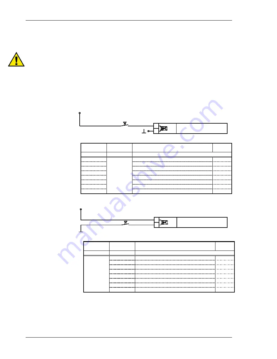
Positive Logic
6 to 32 Vdc
Signal device
Discrete input
A
B
Figure 3-2: Discrete inputs - positive logic
Terminal
Associated
common
Description
(according to DIN 40 719, part 3, 5.8.3)
A
max
A
B
5
4
Discrete input 1
2.5 mm²
6
Discrete input 2
2.5 mm²
7
Discrete input 3
2.5 mm²
8
Discrete input 4
2.5 mm²
9
Discrete input 5
2.5 mm²
10
Discrete input 6
2.5 mm²
11
Discrete input 7
2.5 mm²
12
Discrete input 8
2.5 mm²
Negative Logic
Discrete input
A
B
Signal device
6 to 32 Vdc
Figure 3-3: Discrete input - negative logic
Associated
common
Terminal
Description
(according to DIN 40 719, part 3, 5.8.3)
A
max
A
B
4
5
Discrete input 1
2.5 mm²
6
Discrete input 2
2.5 mm²
7
Discrete input 3
2.5 mm²
8
Discrete input 4
2.5 mm²
9
Discrete input 5
2.5 mm²
10
Discrete input 6
2.5 mm²
11
Discrete input 7
2.5 mm²
12
Discrete input 8
2.5 mm²