


Manual 37135C
IKD 1 - Digital I/O Expansion Board
Page 10/41
© Woodward
Interface
≡≡≡≡≡≡≡≡≡≡≡≡≡≡≡≡≡≡≡≡≡≡≡≡≡
CAN Bus
Connection
In
ter
fac
e
CA
N
bu
s
CA
N-
L
Te
rm
inat
ion
CA
N-
H
G
ND
C
A B
D E
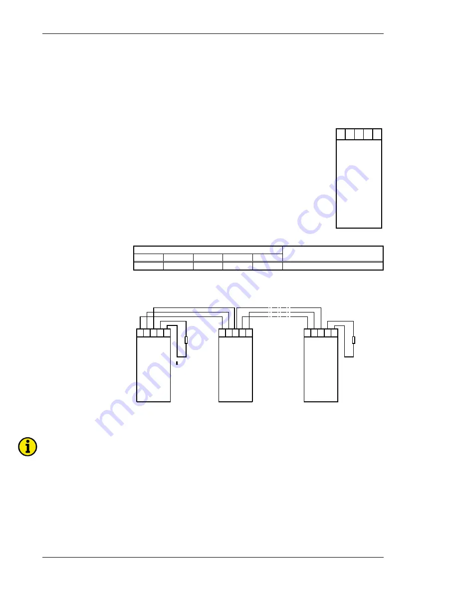
Figure 3-5: Interface - Terminals
Terminal
Description
A
(18)
B
(17)
C
(16)
D
(15)
E
(14)
[1]
[1]
GND
CAN-H
CAN-L CAN bus
[1]..could be used to loop CAN bus and/or to connect termination resistance.
Bus Structure
Terminal
resistance
Note:
The termination must be
effected with a resistor
which corresponds to the
wave impedance of the
used cable (e. g. 120 )
CAN bus
CA
N-
H
CA
N-
L
GN
D
Ter
m
inat
io
n
Ω
CAN bus
CA
N-
H
Terminal
resistance
CA
N-
L
CA
N-
H
CA
N-
L
GN
D
CA
N-
L
CA
N-
H
CAN bus
Ter
m
inat
io
n
GN
D
Figure 3-6: Interface - loop of CAN bus
NOTE
The CAN bus must be terminated with an impedance which corresponds to the wave impedance of the
cable (e.g. 120 Ohm). The terminating resistor is positioned between CAN-H and CAN-L.