


48
WILO SE 10/2022 V05 DIN A4
English
MAINTENANCE AND REPAIR
6. Carefully pull the impeller (9) off the shaft (10). Make
sure that the key (11) remains in the groove.
7. Clean the shaft (10) and key (11).
8. Push a new impeller (9) onto the shaft (10). Make sure
that the sliding surfaces are not damaged and that the
key (11) is pushed into the groove on the impeller (9)!
9. Fit a new screw locking device (8) and a new washer (7)
to a new fastening screw (6). Screw the fastening screw
(6) back in. Secure the impeller (9) and tighten the fas-
tening screw (6) tightly.
10. Change the O-ring (12) on the bearing bracket of the
back pull-out unit.
11. Push the back pull-out unit back onto the stud bolts on
the hydraulics housing and secure it with the hexagon
nuts (5).
12.
Secure the support (3) to the flange again with the fas
-
tening screw (4).
13.
Test: It must be possible to turn the impeller by hand.
Warning! Sharp edges!
Sharp edges can form on the opening of the suction port.
There is a risk of injury! Wear the necessary protective
clothing, such as protective gloves.
8.4.4. Changing the mechanical seal
Great care must be taken during this task. The mechanical
seal is a very sensitive component that will be destroyed if
incorrect forces are applied to it. This work must be carried
out by trained personnel or Wilo customer service.
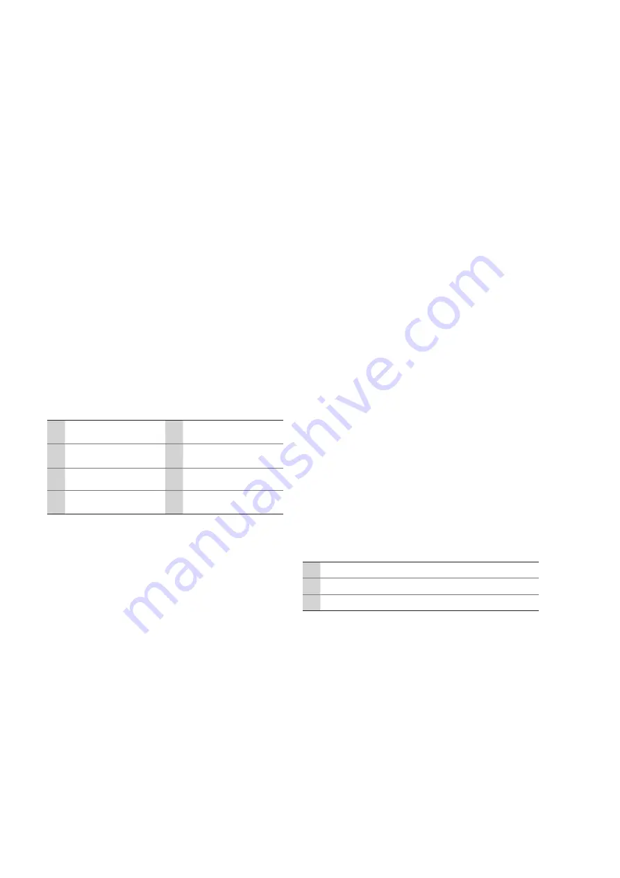
Fig. 7.: Component overview
10 Shaft
14 Rubber bellows with
spring
11 Key
15 Stationary ring with
angle collar
12 O-ring
13 Housing cover
16 Fastening screw for
housing cover
1. Drain the oil from the sealing chamber – see section “Oil
change in sealing chamber”
2. Dismantle the impeller – see section “Impeller change”
3. Remove the key (11).
4. Carefully and slowly pull the rubber bellows and spring
(14) (rotating part of the mechanical seal) off the shaft
(10).
Caution!
Avoid tilting! Otherwise the shaft may be damaged.
5. Loosen the four fastening screws (16) on the housing
cover and completely unscrew them.
6. Carefully and slowly pull the housing cover (13) off the
shaft.
Caution!
Avoid tilting! Otherwise the shaft may be damaged.
7. Press the stationary ring with angle collar (15) (station-
ary part of the mechanical seal) out of its seat in the
bearing bracket cover (13).
8. Clean the shaft (10) and housing cover (13) thoroughly
and check for wear and corrosion.
If the components are damaged, please contact Wilo cus-
tomer service!
9. Unpack the new mechanical seal and check for damage.
Faulty parts must not be installed!
10. To reduce friction during installation, lubricate the shaft,
the seat on the bearing bracket cover and the two com-
ponents of the mechanical seal with low surface tension
water (with dishwashing detergent added) or pure dish-
washing detergent.
Caution!
Never use oil or grease as lubricants!
11. Applying an even distribution of pressure, press the
stationary ring with angle collar (15) into its seat in the
housing cover (13).
12. Fit a new O-ring (12) to the housing cover (13), carefully
and slowly push it onto the shaft (10) and secure it again
with the four fastening screws (16).
Caution!
Avoid tilting! Otherwise the shaft or sliding surface of the
mechanical seal may be damaged!
13. Slide the rubber bellows with spring (14) onto the shaft
(10), turning it slightly clockwise until it is completely in
contact with the stationary ring (15).
Caution!
Avoid tilting! For longer distances, remoisten frequently.
Only apply force to the last turn of the spring!
14. Insert the key (11) again.
15. Install the impeller – see section “Impeller change”
8.4.5. Change of hydraulics
To change the hydraulics, proceed as described in the
“Removal” chapter. To do so, remove the back pull-out unit
and then replace the hydraulics housing in the piping.
8.4.6. Change of motor
The system is driven as standard by IEC standard motors.
These can be replaced at any time. See the type designation
for the size; the B5 motor construction is used.
Fig. 8.: Removal of the motor
1 Standard motor
2
Hexagon nuts for fixation of the motor
3
Hexagon head screws for fixation of the motor
1. Fasten the lifting equipment to the marked attachment
points.
2. Loosen and remove hexagon nuts.
3.
Press the hexagon head screws out of the flange.
4. Carefully pull or lift off the motor from the hydraulic
flange.
5.
Place a new motor on the hydraulic flange.
Pay attention to the sliding surfaces of the motor shaft.
6.
Insert hexagon head screws into the flange
7. Attach hexagon nuts with washers to the hexagon head
screws and screw them tight.


