51
Typically, the same source is assigned across each programmable
selector button, like EXT 1 set for a pre-delay processed air signal; EXT 2
set for an off-air tuner to verify you’re still broadcasting; TEL set to
monitor the Telco Mix output; and SOFT set for another often-monitored
source. Engineering must identify what source is assigned to each switch.
CR Column
The CR/HDPN (Control Room/Headphone) column has eight monitor
select buttons to select between the four program buses (PGM 1, PGM 2,
PGM 3, and PGM 4) and four engineering-assigned sources (EXT 1, EXT 2,
TEL, and SOFT) to set the audio being monitored in the control room. A lit
button indicates which source is going to the control room monitor
speakers and to the board operator’s headphone jack. The current source
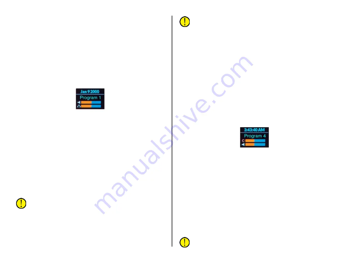
name is also shown in green in the CR Display (Figure 4-8).
Figure 4-8 Monitor Control Panel - CR Display
A “wild” or on-the-fly source can quickly be selected for the CR monitors
by clicking the CR Source Selector. The CR Display changes to show the
list of available sources. Rotate the source selector to highlight the desired
source name then click the selector to choose that source. Its name is
shown in red to indicate it’s a wild source. A wild source can also be
assigned by a console event or salvo and its name will also be in red if it’s
not a source assigned to the eight selector buttons.
Split Cue
Split Cue sets how cue audio is auto-switched into the board operator
headphones. When lit, and a channel has a lit cue button, cue audio is fed
to the left ear while the CR monitor audio is summed to mono and fed to
the right ear. For air studios, the Split Cue is typically lit. When Split Cue is
unlit, cue is auto-switched to both ears (stereo cue) cutting off the CR
monitor source audio. This is the normal setting for production rooms
where monitoring the PGM 1 or air signal is not as critical.
Note: Auto-switching of cue into the board operator headphones is
a console setup option so is not under board operator control.
Faders
The left fader (CR) controls the level of the control room monitor
speakers. Its level is shown in the upper bar graph (with the speaker icon)
in the CR display (Figure 4-8). The right fader (HDPN) controls the volume
of the board operator headphones. Its level is shown in the lower bar
graph (with the headphone icon) in the CR display.
Note: The board operator headphones plug into a recessed 1/4"
TRS jack in the Surface’s right side panel.
CR Display
The CR display (Figure 4-8) shows the date above the white line and the
current CR monitor source below the white line. If the monitor source
name is green it indicates that it’s a source on a CR monitor select button
(that button is also lit). If the monitor name is red it indicates an on-the-
fly monitor source selected using the CR Source Selector or other method,
in which case no CR monitor select button will be lit.
The Control Room monitor speakers and the cue speakers are
automatically muted, and an on-air warning light triggered, whenever a
control room microphone is turned on. A red X appears over the CR
monitor speaker icon and the cue level icon (the C bar graph in the Studio
Display) to indicate muting while a control room microphone is on.
Studio Column
The Studio column also has eight monitor select buttons to choose
between monitoring the four program buses and four engineering-set
sources. A lit button indicates that source is going to the studio monitor
speakers. The current studio monitor source is shown in green (or in red if
it’s a wild source) in the Studio Display (Figure 4-9)
Figure 4-9 Monitor Control Panel – Studio Display
An on-the-fly source can quickly be selected for the studio monitors by
clicking the Studio Source Selector. The Studio Display changes to show
the list of available sources. Rotate the source selector to highlight the
desired source name then click the selector to choose that source. Its
name is shown in red to indicate it’s a wild source. If a wild source is
assigned by a console event or salvo the studio monitor source name will
also be red and no studio select button will be lit.
TB to CR
The Talkback to Control Room control adjusts the level of studio or
external mics talking to the control room using a talent station or remote
talkback switch. Its level is shown in the upper bar graph (TBR) in the
Meter Display (Figure 4-10 on page 52). The talkback audio uses the cue
system so the cue button lights on the studio/external mic channel while
talkback is active. This also means the Cue Level control affects the
talkback level along with the TB to CR control.
Note: Talkback audio will not be heard in the board operator
headphones unless cue is set to auto-switch into the headphones.


