19
Input Trim/Gain/Balance Adjustment
PR&E Navigator has level controls for each physical input and output on
the Mix Engine and Razor. Up to 18 dB of gain, or 18 dB of trim, from
unity gain (0 dB), can be applied in real time to the audio. Viewing and
adjusting the level controls for the inputs is done in the Blade > Sources
tab for each Blade. The outputs are viewed and adjusted in the Blade >
Destinations tab for each Blade. See page 40 for details.
Monitor Muting & Hot Mic Logic
Although any signal can be set to mute the monitor outputs, typically
only mics are set to mute outputs. For Control Room mics you’ll want to
mute the CR and CUE outputs, unless Cue only feeds the studio, in which
case the Studio mics would be set to mute the STU and CUE outputs.
These settings are made using the EMX Surface Setup app’s VDips page
tab. See page 26 for details.
Setting Monitor & Meter Button Sources
The EMX Surface’s Monitor Control panel has three columns of controls:
Control Room (CR); Studio; and Meter (see Figure 4-7 on page 50). The
top of each column has a large knob source selector. Just in front of each
source selector are four source select buttons. For the CR and Studio
columns the buttons are labeled: EXT 1, EXT 2, TEL, and SOFT. The four
Meter column buttons are labeled: EXT 1, EXT 2, TEL, and PGM 4. Of these
twelve buttons, only the Meter PGM 4 button is a dedicated source, the
other eleven buttons have user-assigned sources. The list of sources that
can be assigned to the buttons is set using the EMX Surface Setup app’s
Visibilities page tab (page 30).
To assign a source, press/hold the select button for about three seconds,
until it begins blinking. That column’s display switches to show the list of
available sources. Use that column’s source selector to highlight the
desired source then click the source selector to assign the highlighted
source to the blinking button. The display returns to show the normal
display. To check that the correct source was assigned press the select
button. The assigned source will appear in green in that column’s display.
RAZOR I/O INTERFACE NOTES
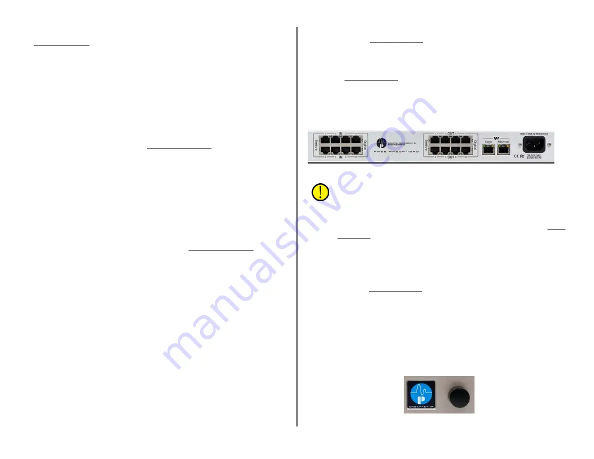
Each Razor has eighteen RJ45 connectors: eight have the audio inputs;
eight have the audio outputs; one has the Logic LIO; and one (Ethernet)
connects the Razor to a PR&E Mix Engine Ethernet switch port or to a
facility AoIP switch in a larger PRE-IP network.
On a Razor 16A, sixteen RJ45 connectors are used for the analog inputs
and outputs, each carrying two analog signals (stereo or dual mono). The
Razor 16A also has two built-in mic preamps, like the PR&E Mix Engine, so
it also has two female XLR Mic Inputs and one Mics Out RJ45 jack, which
is connected to an Analog Input using a short CAT5 patch cord. That input
would then need to be split into two mono inputs from its default stereo
setting using the PR&E Navigator (see Changing Signal Type on page 39
for details on splitting a stereo input or output into dual mono signals).
On the Razor 16D, the sixteen RJ45 inputs and outputs each carry one
stereo AES/EBU signal. Any input or output can also be split into two mono
signals in PR&E Navigator (page 39).
On the Razor 16AD (rear panel shown in Figure 2-10) the first four
RJ45 jacks (IN 1–4) are stereo analog inputs. The remaining four RJ45 IN
jacks (IN 5–8) have four stereo AES/EBU inputs. The first four RJ45 OUT
jacks have the analog outputs (OUT 1–4) while the last four RJ45 jacks
(OUT 5–8) have the stereo AES/EBU signals.
Figure 2-10 Razor 16AD rear panel connections
Note: The Razor’s Ethernet AoIP jack has eight paired incoming
and eight paired outgoing audio streams. When a Razor input or
output is split into two mono signals, each mono signal consumes
one of the eight audio streams going into or out of the Razor. This
means that if four stereo inputs or outputs are split into eight
mono signals, and all of those mono signals are connected in PR&E
Navigator, the remaining four stereo inputs or outputs cannot be
used simultaneously because all eight audio streams would already
be consumed by the eight mono signals.
LOGIC - The RJ45 Logic connector is used to connect hard-wired logic to
external devices like warning light interfaces and tallies. Each Logic
connector is wired per Figure 2-4 on page 12. The logic connections are
configured using PR&E Navigator as either a logic input or output with an
assigned logic function.
FRONT PANEL DISPLAY & CONTROL - The Razor has a front panel
OLED display and a rotary encoder (Figure 2-11). The encoder is used to
step through the four screens that can be displayed on the Razor. One
screen shows the levels for that Razor’s inputs. A second screen shows the
eight stereo output levels. The other two screens show technical details for
that Razor like its system name, IP address, MAC address, and version of
code that’s running on that Razor.
Figure 2-11 Razor front panel OLED and Encoder


