


page 6 – 3
D-9 / Jan 2006
H A R D W A R E
Mixer Link Wiring
This RJ-45 (or optical) connection provides the control link between the control
surface and the Bridge Router system. All settings and commands generated on the
control surface pass through this link. A special CAT-5 cable wired in “crossover”
fashion is used for this link. This special cable connects the RJ-45 jack on the control
surface to the matching RJ-45 jack on the Bridge Router system. Please note that, in a
typical system, there will be many RJ-45 jacks in the Bridge Router, and for proper
operation, the control surface must be connected to the specific RJ-45 jack defined for
it in the system configuration.
Internal Programming Options
All internal programming options are made via PCB mounted dipswitches.
Switch Settings
DIPSW1 - SW4 & SW9 - Not Used
The four positions of dipswitches SW1-SW4 and SW9 are reserved for future use.
SW5 - SW8 - CAT5 vs. Fiber & Transceiver Select
These slide switches can be used to select the CAT5 or fiber optic mixer link
connection.
To set MIXER LINK 1 for CAT 5 connection slide switches SW6 - TX and
SW8 - RX to the up position (toward the surface’s rear). Sliding these switches down
selects fiber optic connection for transceiver 1.
To set MIXER LINK 2 for CAT 5 connection slide switches SW5 - TX and
SW7 - RX to the up position (toward the surface’s rear). Sliding these switches down
selects fiber optic connection for transceiver 2.
Note that the setting of these switches and SW12 pos 4 (see below) must be made
to the same selection. The Mixer Link is either CAT5 or FIBER.
SW10 - Master Reset
This switch can be used to force takeover by the backup CPU if the main CPU has
failed and automatic failover has not been accomplished.
SW11 - CPU Reset
This switch can be used to reset the host controller’s main CPU without powering
down the system. If the system is running from the backup CPU this switch will NOT
cause the main CPU to take over again. To do that you must recycle the surface power.
SW12 Position 1 - Sample Rate
This dipswitch position must be set to agree with the sample rate of the system. The
switch is off for a sample rate of 44.1kHz and on for a sample rate of 48kHz.
SW12 Position 2 - Not Used
This dipswitch position is reserved for future use.
D-9 / Jul 2009
!
All devices in the
system must be
set to the same
sample rate!
Содержание D-9
Страница 1: ...D 9 Digital Control Surface TECHNICAL MANUAL 600 Industrial Drive New Bern North Carolina USA 28562 ...
Страница 63: ...D 9 May 2005 page 7 2 ...
Страница 64: ...D 9 May 2005 page 7 3 ...
Страница 65: ...D 9 May 2005 page 7 4 ...
Страница 66: ...D 9 May 2005 page 7 5 ...
Страница 67: ...page 7 6 D 9 May 2005 ...
Страница 68: ...D 9 May 2005 page 7 7 ...
Страница 69: ...page 7 8 IP 9 4 Inputs Panel Switch Card Load Sheet D 9 May 2005 ...
Страница 70: ...page 7 9 D 9 Oct 2003 ...
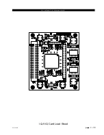
Страница 71: ...page 7 2 D 9 Oct 2003 S C H E M A T I C D R A W I N G S IQ 9 IQ Card Load Sheet page 7 10 ...
Страница 72: ...page 7 11 D 9 Oct 2003 ...
Страница 73: ...page 7 12 D 9 Oct 2003 ...
Страница 74: ...page 7 13 D 9 Oct 2003 ...
Страница 75: ...page 7 14 D 9 Oct 2003 ...
Страница 76: ...page 7 15 D 9 Oct 2003 ...
Страница 77: ...page 7 16 MN 9 Control Panel Switch Card Load Sheet D 9 Oct 2003 ...
Страница 78: ...D 9 May 2005 page 7 17 ...
Страница 79: ...D 9 May 2005 page 7 18 ...
Страница 80: ...page 7 19 MFS 9 4 Master Panel Switch Card Load Sheet D 9 May 2005 ...
Страница 84: ...D 9 Oct 2003 page 7 23 ...
Страница 85: ...D 9 Oct 2003 page 7 24 ...
Страница 86: ...D 9 Oct 2003 page 7 25 ...
Страница 87: ...page 7 26 DCM 9 DCM Panel Switch Card Load Sheet D 9 Oct 2003 ...
Страница 95: ...page 7 34 HC 9 Host Controller Card Load Sheet D 9 Apr 2008 ...
Страница 96: ...page 7 35 D 9 Oct 2003 ...
Страница 97: ...page 7 36 BP 9 Back Plane Card Load Sheet D 9 Oct 2003 ...
Страница 98: ...page 7 37 D 9 Oct 2003 ...
Страница 99: ...page 7 4 D 9 Oct 2003 S C H E M A T I C D R A W I N G S BPR 9 Back Plane Repeater Card Load Sheet page 7 38 ...
Страница 100: ...D 9 Oct 2003 page 7 39 ...
Страница 101: ...page 7 5 D 9 Oct 2003 S C H E M A T I C D R A W I N G S 32VC5 5 5V DC to DC Converter Card Load Sheet page 7 40 ...
Страница 102: ...D 9 Oct 2003 page 7 41 ...
Страница 103: ...page 7 6 D 9 Oct 2003 S C H E M A T I C D R A W I N G S VU 9 VU Receiver Card Load Sheet page 7 42 ...
Страница 104: ...page 7 43 D 9 Oct 2003 ...
Страница 105: ...page 7 7 D 9 Oct 2003 S C H E M A T I C D R A W I N G S page 7 44 SW1 700 Switch Card Load Sheet ...
Страница 106: ...page 7 45 D 9 Oct 2003 ...
Страница 107: ...page 7 8 D 9 Oct 2003 S C H E M A T I C D R A W I N G S PWI 5 1 Power Interface Card Load Sheet page 7 46 ...