


C O N T R O L P A N E L
page 3 – 3
D-9 / Oct 2003
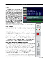
• A source can also be loaded as a monitor
preset by first selecting it with the SELECT
knob and the SOURCE display, and then hold-
ing the PRESET button down until the source
shows in the PROGRAMMABLE PRESET
display. That source can then be monitored by
pressing the PRESET button.
To select a source for a monitor by one of
the above methods, first press the SET button
next to the knob for the desired monitor.
The knob controls the level of the monitor
signal.
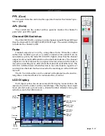
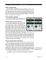
Control Room Section
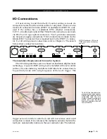
In a typical radio or television application the control surface is located in
the audio control room. Speakers in the control room allow the control surface
operator to listen to the various control surface bus outputs to be assured that
the control surface is performing as desired. These speakers are fed by a stereo
or 5.1 signal routed from the control surface’s control room output. In
addition to the control room output, the operator may also desire to listen to
specific isolated faders via the cue system and the external cue speaker, or
may want to listen via headphones.
In some instances the control surface operator may also be performing
talent whose voice will be heard over the radio. The operator’s microphone
may thus provide a part of the signal that is going out over the air. If that signal
is the one being monitored with the control room speakers, there is the
potential for feedback. The amplified signal from the control room speakers
is picked up by the microphone and reamplified to a new, higher, level, which
then is once again picked up by the microphone. The signal quickly rises to
an ear-splitting screech. To prevent this, the operator’s microphone is
normally set in the configuration software to MUTE the control room output
to prevent the occurrence of feedback.
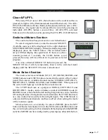
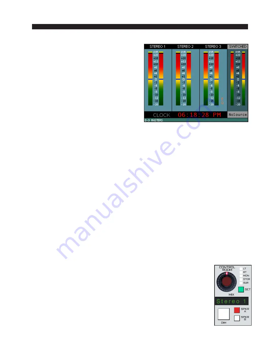
CR SET BUTTON - lets the operator select the source to be listened to in
the control room speakers.
CR DISPLAY - the eight character display shows the source that is
selected for monitoring in the control room.
CR LEVEL CONTROL - determines the overall loudness of the signal
being monitored as it appears in the control room speakers.
DIM BUTTON - lets the operator “dim” the control room speakers (drop
in level). Actual DIM level is set by the DIM encoder at the top of this panel.
MODE INDICATOR - a set of five LEDs indicates which mode, LEFT,
RIGHT, MONO, STEREO, or SURROUND, the CR signal is operating in
(see also page 3-5).
SPKR A, SPKR B - these two switches are used to determine which of two
outputs will be fed by the CR signal. Each feed may have its mode pro-
grammed separately (see Selecting Output Mix Destinations on page 3-11).
D-9 / Jan 2007
Содержание D-9
Страница 1: ...D 9 Digital Control Surface TECHNICAL MANUAL 600 Industrial Drive New Bern North Carolina USA 28562 ...
Страница 63: ...D 9 May 2005 page 7 2 ...
Страница 64: ...D 9 May 2005 page 7 3 ...
Страница 65: ...D 9 May 2005 page 7 4 ...
Страница 66: ...D 9 May 2005 page 7 5 ...
Страница 67: ...page 7 6 D 9 May 2005 ...
Страница 68: ...D 9 May 2005 page 7 7 ...
Страница 69: ...page 7 8 IP 9 4 Inputs Panel Switch Card Load Sheet D 9 May 2005 ...
Страница 70: ...page 7 9 D 9 Oct 2003 ...
Страница 71: ...page 7 2 D 9 Oct 2003 S C H E M A T I C D R A W I N G S IQ 9 IQ Card Load Sheet page 7 10 ...
Страница 72: ...page 7 11 D 9 Oct 2003 ...
Страница 73: ...page 7 12 D 9 Oct 2003 ...
Страница 74: ...page 7 13 D 9 Oct 2003 ...
Страница 75: ...page 7 14 D 9 Oct 2003 ...
Страница 76: ...page 7 15 D 9 Oct 2003 ...
Страница 77: ...page 7 16 MN 9 Control Panel Switch Card Load Sheet D 9 Oct 2003 ...
Страница 78: ...D 9 May 2005 page 7 17 ...
Страница 79: ...D 9 May 2005 page 7 18 ...
Страница 80: ...page 7 19 MFS 9 4 Master Panel Switch Card Load Sheet D 9 May 2005 ...
Страница 84: ...D 9 Oct 2003 page 7 23 ...
Страница 85: ...D 9 Oct 2003 page 7 24 ...
Страница 86: ...D 9 Oct 2003 page 7 25 ...
Страница 87: ...page 7 26 DCM 9 DCM Panel Switch Card Load Sheet D 9 Oct 2003 ...
Страница 95: ...page 7 34 HC 9 Host Controller Card Load Sheet D 9 Apr 2008 ...
Страница 96: ...page 7 35 D 9 Oct 2003 ...
Страница 97: ...page 7 36 BP 9 Back Plane Card Load Sheet D 9 Oct 2003 ...
Страница 98: ...page 7 37 D 9 Oct 2003 ...
Страница 99: ...page 7 4 D 9 Oct 2003 S C H E M A T I C D R A W I N G S BPR 9 Back Plane Repeater Card Load Sheet page 7 38 ...
Страница 100: ...D 9 Oct 2003 page 7 39 ...
Страница 101: ...page 7 5 D 9 Oct 2003 S C H E M A T I C D R A W I N G S 32VC5 5 5V DC to DC Converter Card Load Sheet page 7 40 ...
Страница 102: ...D 9 Oct 2003 page 7 41 ...
Страница 103: ...page 7 6 D 9 Oct 2003 S C H E M A T I C D R A W I N G S VU 9 VU Receiver Card Load Sheet page 7 42 ...
Страница 104: ...page 7 43 D 9 Oct 2003 ...
Страница 105: ...page 7 7 D 9 Oct 2003 S C H E M A T I C D R A W I N G S page 7 44 SW1 700 Switch Card Load Sheet ...
Страница 106: ...page 7 45 D 9 Oct 2003 ...
Страница 107: ...page 7 8 D 9 Oct 2003 S C H E M A T I C D R A W I N G S PWI 5 1 Power Interface Card Load Sheet page 7 46 ...