


G E N E R A L I N F O R M A T I O N
page 1 – 6
D-9 / Oct 2003
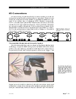
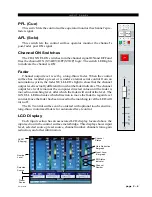
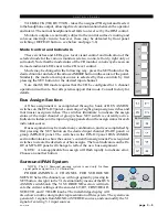
The AMP tool insulation dis-
placement connector system.
Note the right angle hood with
self-locking tabs. The tool,
multipin connectors (with gold
plated pins) and latching
hoods are supplied with each
control surface.
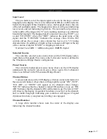
I/O Connections
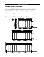
All user wiring to and from the D-9 control surface is made via
connectors located on the control surface’s rear panel. There are also
two RJ-45 connectors for main (ENET A) and failsafe (ENET B - only
used if the surface has a redundant CPU) ethernet connections.
CAT-5 or multi-mode optical fiber Mixer Link connections are made
via RJ-45 or LC type optical connectors. Two 5-pin male connectors
are for power supply connections. VGA connections are made via the
female DB-15 connector that is mounted next to the ENET A connec-
tor. For all wiring pinout connections refer to Chapter 6. The sketch
below shows connector locations.
The Insulation Displacement Connector System
The I/O wiring interface system is based on insulation displacement
technology. A special AMP wiring tool is included with each control
surface; it is auto-indexing, and allows individual wire connections to
be positively made with a single squeeze of the tool's trigger. The
trigger action is ratchet controlled, and will not release until a full
connection is made. Once released, the multipin connector held in the
tool's jaw automatically indexes to the next connector pin. The technol-
NOTE: Keyboard, VGA, and
COM connectors for factory
use only.
D-9 / Mar 2008
ENET A
RJ-45
ENET B
RJ-45
KEYBOARD
NOT
USED
DB-9
DB-9
NOT
USED
VGA
DB-15
CAT5
FIBER
MIXER LINK
RJ-45
OPTO
POWER A
POWER B
NOT USED
Содержание D-9
Страница 1: ...D 9 Digital Control Surface TECHNICAL MANUAL 600 Industrial Drive New Bern North Carolina USA 28562 ...
Страница 63: ...D 9 May 2005 page 7 2 ...
Страница 64: ...D 9 May 2005 page 7 3 ...
Страница 65: ...D 9 May 2005 page 7 4 ...
Страница 66: ...D 9 May 2005 page 7 5 ...
Страница 67: ...page 7 6 D 9 May 2005 ...
Страница 68: ...D 9 May 2005 page 7 7 ...
Страница 69: ...page 7 8 IP 9 4 Inputs Panel Switch Card Load Sheet D 9 May 2005 ...
Страница 70: ...page 7 9 D 9 Oct 2003 ...
Страница 71: ...page 7 2 D 9 Oct 2003 S C H E M A T I C D R A W I N G S IQ 9 IQ Card Load Sheet page 7 10 ...
Страница 72: ...page 7 11 D 9 Oct 2003 ...
Страница 73: ...page 7 12 D 9 Oct 2003 ...
Страница 74: ...page 7 13 D 9 Oct 2003 ...
Страница 75: ...page 7 14 D 9 Oct 2003 ...
Страница 76: ...page 7 15 D 9 Oct 2003 ...
Страница 77: ...page 7 16 MN 9 Control Panel Switch Card Load Sheet D 9 Oct 2003 ...
Страница 78: ...D 9 May 2005 page 7 17 ...
Страница 79: ...D 9 May 2005 page 7 18 ...
Страница 80: ...page 7 19 MFS 9 4 Master Panel Switch Card Load Sheet D 9 May 2005 ...
Страница 84: ...D 9 Oct 2003 page 7 23 ...
Страница 85: ...D 9 Oct 2003 page 7 24 ...
Страница 86: ...D 9 Oct 2003 page 7 25 ...
Страница 87: ...page 7 26 DCM 9 DCM Panel Switch Card Load Sheet D 9 Oct 2003 ...
Страница 95: ...page 7 34 HC 9 Host Controller Card Load Sheet D 9 Apr 2008 ...
Страница 96: ...page 7 35 D 9 Oct 2003 ...
Страница 97: ...page 7 36 BP 9 Back Plane Card Load Sheet D 9 Oct 2003 ...
Страница 98: ...page 7 37 D 9 Oct 2003 ...
Страница 99: ...page 7 4 D 9 Oct 2003 S C H E M A T I C D R A W I N G S BPR 9 Back Plane Repeater Card Load Sheet page 7 38 ...
Страница 100: ...D 9 Oct 2003 page 7 39 ...
Страница 101: ...page 7 5 D 9 Oct 2003 S C H E M A T I C D R A W I N G S 32VC5 5 5V DC to DC Converter Card Load Sheet page 7 40 ...
Страница 102: ...D 9 Oct 2003 page 7 41 ...
Страница 103: ...page 7 6 D 9 Oct 2003 S C H E M A T I C D R A W I N G S VU 9 VU Receiver Card Load Sheet page 7 42 ...
Страница 104: ...page 7 43 D 9 Oct 2003 ...
Страница 105: ...page 7 7 D 9 Oct 2003 S C H E M A T I C D R A W I N G S page 7 44 SW1 700 Switch Card Load Sheet ...
Страница 106: ...page 7 45 D 9 Oct 2003 ...
Страница 107: ...page 7 8 D 9 Oct 2003 S C H E M A T I C D R A W I N G S PWI 5 1 Power Interface Card Load Sheet page 7 46 ...