


I N P U T P A N E L
page 2 – 3
D-9 / Oct 2003
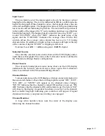
Gain Control
The GAIN level control controls mic or line gain for the selected
input source. If the channel’s SET buttons is pressed, the relative gain
setting can be read from one of the LCD screens (see page 2-4).
Phantom Power
The PHAN On/Off switch applies phantom voltage to any selected
microphone. The phantom power attribute stays ON even when the
microphone is not selected on the control surface.
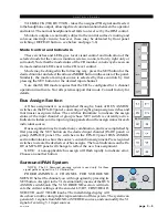
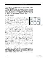
AUX
The D-9 Control Surface has
(2) AUX encoders, (2) bank select
switches (AUX 1/2 and AUX 3/4),
and (3) mode switches (ON, PRE
FDR, and PRE ON) for control-
ling the (4) AUX SEND buses.
Operation is as follows: first
“DOBBY” or momentarily press
one of the encoders to select which
group of AUX SENDS (AUX 1/2
or AUX 3/4) is being worked on.
The LED at the bottom center 6 o’clock position of the encoder knob
will light to indicate the active group. Pressing the bank select button
will select which AUX SEND within the group is being worked on. A
lighted switch indicates you are working on an even numbered group
(2 or 4). Once the desired AUX SEND has been selected using these
controls, the ON, PRE FDR, and PRE ON switches and the encoder can
be adjusted for that particular AUX SEND (without pressing down the
encoder, turning it adjusts the level of that channel in the aux send;
turning it while pressing the knob down pans the channel between the
left and right sides of the stereo aux send bus). Subsequently, the bank
select switch can be pressed or the encoder “DOBBIED” to choose the
next AUX SEND, and so on.
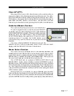
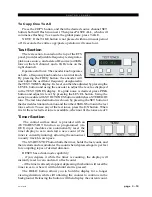
Mode Selector Indicator
MODE selection switches in the EFS CONTROL panel (see
Chapter 3) enable input channels to operate in Mono, Left only, Right
only, Blend, and Stereo. The switch lights up to indicate the selected
mode. This feature is activated for a given channel by pressing the
channel’s SET button (see page 2-4).
Pan/Balance Knob
The LT/RT knob (5.1 SURR section in the EFS CONTROL
panel) acts as a panpot in MONO, LEFT only and RIGHT only
modes, and as a balance control in STEREO mode. In BLEND, both
the left and right input signals are sent to both the left and right sides
of assigned stereo destinations, with the LT/RT knob acting as a mix
EFS-D9 Control Panel
Tip: DOBBY (pronounce
dah-bee) - means to
quickly press and release
an encoder knob.
Содержание D-9
Страница 1: ...D 9 Digital Control Surface TECHNICAL MANUAL 600 Industrial Drive New Bern North Carolina USA 28562 ...
Страница 63: ...D 9 May 2005 page 7 2 ...
Страница 64: ...D 9 May 2005 page 7 3 ...
Страница 65: ...D 9 May 2005 page 7 4 ...
Страница 66: ...D 9 May 2005 page 7 5 ...
Страница 67: ...page 7 6 D 9 May 2005 ...
Страница 68: ...D 9 May 2005 page 7 7 ...
Страница 69: ...page 7 8 IP 9 4 Inputs Panel Switch Card Load Sheet D 9 May 2005 ...
Страница 70: ...page 7 9 D 9 Oct 2003 ...
Страница 71: ...page 7 2 D 9 Oct 2003 S C H E M A T I C D R A W I N G S IQ 9 IQ Card Load Sheet page 7 10 ...
Страница 72: ...page 7 11 D 9 Oct 2003 ...
Страница 73: ...page 7 12 D 9 Oct 2003 ...
Страница 74: ...page 7 13 D 9 Oct 2003 ...
Страница 75: ...page 7 14 D 9 Oct 2003 ...
Страница 76: ...page 7 15 D 9 Oct 2003 ...
Страница 77: ...page 7 16 MN 9 Control Panel Switch Card Load Sheet D 9 Oct 2003 ...
Страница 78: ...D 9 May 2005 page 7 17 ...
Страница 79: ...D 9 May 2005 page 7 18 ...
Страница 80: ...page 7 19 MFS 9 4 Master Panel Switch Card Load Sheet D 9 May 2005 ...
Страница 84: ...D 9 Oct 2003 page 7 23 ...
Страница 85: ...D 9 Oct 2003 page 7 24 ...
Страница 86: ...D 9 Oct 2003 page 7 25 ...
Страница 87: ...page 7 26 DCM 9 DCM Panel Switch Card Load Sheet D 9 Oct 2003 ...
Страница 95: ...page 7 34 HC 9 Host Controller Card Load Sheet D 9 Apr 2008 ...
Страница 96: ...page 7 35 D 9 Oct 2003 ...
Страница 97: ...page 7 36 BP 9 Back Plane Card Load Sheet D 9 Oct 2003 ...
Страница 98: ...page 7 37 D 9 Oct 2003 ...
Страница 99: ...page 7 4 D 9 Oct 2003 S C H E M A T I C D R A W I N G S BPR 9 Back Plane Repeater Card Load Sheet page 7 38 ...
Страница 100: ...D 9 Oct 2003 page 7 39 ...
Страница 101: ...page 7 5 D 9 Oct 2003 S C H E M A T I C D R A W I N G S 32VC5 5 5V DC to DC Converter Card Load Sheet page 7 40 ...
Страница 102: ...D 9 Oct 2003 page 7 41 ...
Страница 103: ...page 7 6 D 9 Oct 2003 S C H E M A T I C D R A W I N G S VU 9 VU Receiver Card Load Sheet page 7 42 ...
Страница 104: ...page 7 43 D 9 Oct 2003 ...
Страница 105: ...page 7 7 D 9 Oct 2003 S C H E M A T I C D R A W I N G S page 7 44 SW1 700 Switch Card Load Sheet ...
Страница 106: ...page 7 45 D 9 Oct 2003 ...
Страница 107: ...page 7 8 D 9 Oct 2003 S C H E M A T I C D R A W I N G S PWI 5 1 Power Interface Card Load Sheet page 7 46 ...