


G E N E R A L I N F O R M A T I O N
page 1 – 7
D-9 / Oct 2003
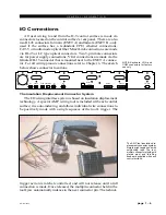
ogy is such that no stripping, soldering, or tinning of wire ends is required;
all that is needed is that the wires destined for the connector be snub cut and
laid out in order (although tubing should be used on bare drain wires). An
empty DB-9 connector is inserted into the tool, indexed to the first pin, and
the wires are inserted one by one into the jaw and the trigger squeezed. In
this way a single multipin connector can be completely wired up in a
minute or two. These connectors will accept wire gauge 22 - 26 AWG.
In the event of a wiring error, connector pins may easily be removed
from the shell with the wire still attached, and inserted into the correct
position. Observe the side of the connector, with the metal part down. You
will see a row of "Vees"—simply press the top of the vee together with a
scribe or other sharp instrument; this will unlock the pin from the shell, and
it can be removed and inserted into the correct position. Spread the vee
apart to lock the pin in the new position. It should never be necessary to
discard a connector due to a wiring error.
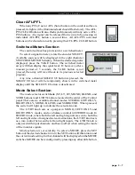
Note that mating hoods for each connector are also supplied with the
system. These have locking screws that hold the connectors securely to
their mates.
D-9 / Jan 2006
Содержание D-9
Страница 1: ...D 9 Digital Control Surface TECHNICAL MANUAL 600 Industrial Drive New Bern North Carolina USA 28562 ...
Страница 63: ...D 9 May 2005 page 7 2 ...
Страница 64: ...D 9 May 2005 page 7 3 ...
Страница 65: ...D 9 May 2005 page 7 4 ...
Страница 66: ...D 9 May 2005 page 7 5 ...
Страница 67: ...page 7 6 D 9 May 2005 ...
Страница 68: ...D 9 May 2005 page 7 7 ...
Страница 69: ...page 7 8 IP 9 4 Inputs Panel Switch Card Load Sheet D 9 May 2005 ...
Страница 70: ...page 7 9 D 9 Oct 2003 ...
Страница 71: ...page 7 2 D 9 Oct 2003 S C H E M A T I C D R A W I N G S IQ 9 IQ Card Load Sheet page 7 10 ...
Страница 72: ...page 7 11 D 9 Oct 2003 ...
Страница 73: ...page 7 12 D 9 Oct 2003 ...
Страница 74: ...page 7 13 D 9 Oct 2003 ...
Страница 75: ...page 7 14 D 9 Oct 2003 ...
Страница 76: ...page 7 15 D 9 Oct 2003 ...
Страница 77: ...page 7 16 MN 9 Control Panel Switch Card Load Sheet D 9 Oct 2003 ...
Страница 78: ...D 9 May 2005 page 7 17 ...
Страница 79: ...D 9 May 2005 page 7 18 ...
Страница 80: ...page 7 19 MFS 9 4 Master Panel Switch Card Load Sheet D 9 May 2005 ...
Страница 84: ...D 9 Oct 2003 page 7 23 ...
Страница 85: ...D 9 Oct 2003 page 7 24 ...
Страница 86: ...D 9 Oct 2003 page 7 25 ...
Страница 87: ...page 7 26 DCM 9 DCM Panel Switch Card Load Sheet D 9 Oct 2003 ...
Страница 95: ...page 7 34 HC 9 Host Controller Card Load Sheet D 9 Apr 2008 ...
Страница 96: ...page 7 35 D 9 Oct 2003 ...
Страница 97: ...page 7 36 BP 9 Back Plane Card Load Sheet D 9 Oct 2003 ...
Страница 98: ...page 7 37 D 9 Oct 2003 ...
Страница 99: ...page 7 4 D 9 Oct 2003 S C H E M A T I C D R A W I N G S BPR 9 Back Plane Repeater Card Load Sheet page 7 38 ...
Страница 100: ...D 9 Oct 2003 page 7 39 ...
Страница 101: ...page 7 5 D 9 Oct 2003 S C H E M A T I C D R A W I N G S 32VC5 5 5V DC to DC Converter Card Load Sheet page 7 40 ...
Страница 102: ...D 9 Oct 2003 page 7 41 ...
Страница 103: ...page 7 6 D 9 Oct 2003 S C H E M A T I C D R A W I N G S VU 9 VU Receiver Card Load Sheet page 7 42 ...
Страница 104: ...page 7 43 D 9 Oct 2003 ...
Страница 105: ...page 7 7 D 9 Oct 2003 S C H E M A T I C D R A W I N G S page 7 44 SW1 700 Switch Card Load Sheet ...
Страница 106: ...page 7 45 D 9 Oct 2003 ...
Страница 107: ...page 7 8 D 9 Oct 2003 S C H E M A T I C D R A W I N G S PWI 5 1 Power Interface Card Load Sheet page 7 46 ...