29
Rev Version 1.4.1
Rev Version 1.4.1
no gateway on the LAN, set the default gateway address to the same address as the
modules IP Address as configured above.
Save Changes Save changes to non-volatile memory. The module will need to be restarted before
the changes take effect.
Save Changes
And Reset
Save settings to non-volatile memory, and reboot the WI-MOD-xxx-E-5W module. Once
the module has completed the reboot sequence, all changes are in effect.
Device Mode
The Device Mode field on the Network page allows you to configure the WI-MOD-xxx-E-5W as either a bridge or a
router. When
“Router” is selected, the screen displays a separate IP address for each interface (Ethernet and
wireless). The default mode is
“Bridge” which only requires one interface IP address.
•
Bridge Operation
—A bridge connects several Ethernet networks together, and makes them appear as a single
Ethernet network to higher protocol layers. By default, the WI-MOD-xxx-E-5W is configured as a transparent
bridge. When a transparent bridge is started, it learns the location of other devices by monitoring the MAC
address of all incoming traffic. Initially it forwards all traffic between the wired Ethernet port and the wireless
port. However, by keeping a list of devices heard on each port, the transparent bridge can decide which traffic
must be forwarded between ports, and it will only transfer a message from the wired port to the wireless port if
it is required.
A bridge will forward all broadcast traffic between the wired and wireless ports. If the wired network is busy
with broadcast traffic, the radio network on the WI-MOD-xxx-E-5W can be unnecessarily overburdened. Use
filtering to reduce broadcast traffic sent over the radio. For information on creating filters, see
“4.10 Filtering” on
page 49.
By default, a transparent bridge does not handle loops within the network. There must be a single path to each
device on the network. Loops in the network will cause the same data to be continually passed around that loop.
Redundant wireless links may be set up by enabling the bridge Spanning Tree Protocol (see
“Bridge STP” on
page 30 for details).
•
Router Operation
—(Routed network.) A router joins separate IP sub-networks together. The router has
different IP addresses on its wired and wireless ports, reflecting the different IP addresses of the separate
Ethernet subnetworks. All of the devices in these separate networks identify the router by IP address as their
gateway to the other network. When devices on one network want to communicate with devices on the other
network, they direct their packets to the router for forwarding.
Because the router has an IP address on each of the networks that it joins, it inherently knows the packet
identity. If the traffic directed at the router cannot be identified for any of the networks to which it is connected,
the router must consult its routing rules as to where to direct the traffic. For details on configuring routing rules,
see
“4.9 IP Routing” on page 48.
Bridge STP
The bridge Spanning Tree Protocol function was introduced to handle network loops and provide redundant paths
in networks. To enable this option, select the Bridge STP checkbox on the Network configuration page.
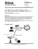
Consider the network in Figure 29, which has a redundant wireless link. If the bridge Spanning Tree Protocol is
enabled, one of the two wireless links will be disabled, and all wireless data will be transferred by one link only. If
the active link fails, the other link will automatically start transferring the wireless data.


