3
3-34 | CFW-11M RB
Installation and Connection
3.4.8 Synchronism
The CFW-11M RB monitors the line voltage (A, B e C) at the converter input with two transformers and a
synchronism board. These signals are used for the regenerative converter control.
Breaker
CFW-11M RB
Line voltage (P0002)
Input voltage (P0007)
Supply
RB control unit
UC11XXXXTYORB
(*)
A
R
B
S
C
T
H1
X2
X2
T1
XC1:1
CSR11
XC
50
XC
50
CC11 RB
H1
H2
X1
X1
T2
2
3
x
4
5
H2
(LC filter)
L Boost
(*)
XXXX: converter rated current.
Y: According to models 4/380-480 V, 5/500-600 V e 6/660-690 V.
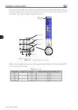
Figure 3.46 -
Synchronism connection diagram
Primary
Secondary
Ground bolt
Figure 3.47 -
Synchronism transformer
Table 3.14 shows the main characteristics for the proper specification of the synchronism transformer.
Table 3.15 -
Synchronism transformer characteristics
CFW-11M RB Model
380 V / 480 V
500 V / 690 V
Rated voltage of the primary H1-H2
480 V
690 V
Transformer ratio N
S
/N
P
1/26
1/35
f (frequency)
50 Hz/60 Hz
S (power)
2.5 VA
Voltage tolerance
± 1 %
Steady state overvoltage
+10 %
Insulation Class
1.1 kV
Class
B
Insulation
Primary to secondary
3000 Vac / 1 min
Primary to shield
3000 Vac / 1 min
Primary to enclosure
3000 Vac / 1 min
Be in accordance wit UL508 standard as the insulation material and manufacturing
Keep the core with low saturation to mantain good linearity between the primary and secondary
Shielding between the primary and secondary: metallic ribbon
Содержание CFW-11M RB
Страница 9: ...1 4 CFW 11M RB 1 Safety Instructions...
Страница 21: ...2 2 12 CFW 11M RB General Instructions...
Страница 87: ...7 7 2 CFW 11M RB Accessories...


