3
3-14 | CFW-11M RB
Installation and Connection
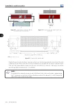
Figure 3.17 -
Lateral section view: detail of the flat
braided cables and fuse connections
Figure 3.18 -
Lateral section view: detail of the DC bus
connections
1
2
1
2
E
E
Inverter
+UD -UD
Note:
dimensions in mm (in).
26
(1.
02
)
26
(1.02)
60 (2.36)
Ø 14 (3x)
(0.55)
60
(2.
36
)
3
0 (
1.1
8)
25
(0.98)
50 (1.97)
8±1
E
Braided wire gauge: AWG-40 (0.08 mm)
17
(0
.67
)
17
(0.67)
Figure 3.19 -
Example of flat braided cable
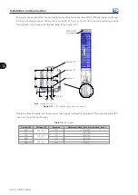
Besides the panel constructive form, some precautions must be taken regarding the connection of the input
cables from the input filter in order to assure equal impedances among the UPs connected in parallel. Figures
3.18 and 3.20 present details in lateral section views of the DC bus (+UD and –UD) output connections
and the input filter connections (R, S, T and GND).
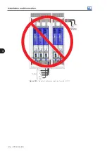
NOTE!
The length of the cables that connect each of the Power Units to the input busbars, represented by
the “F” dimension on the figure 3.20, must be the same for all the phases (R, S and T). Refer to the
table 3.8 for more details on the cables.
Содержание CFW-11M RB
Страница 9: ...1 4 CFW 11M RB 1 Safety Instructions...
Страница 21: ...2 2 12 CFW 11M RB General Instructions...
Страница 87: ...7 7 2 CFW 11M RB Accessories...


