3
3-8 | CFW-11M RB
Installation and Connection
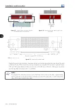
3.3.1 Keypad Installation at the Cabinet Door or Command Panel (Remote keypad)
Note:
dimensions in mm [in].
35.0 [1.38]
28.5 [1.12]
11
3.
0 [
4.
45
]
10
3.0
[4
.0
6]
23
.4
[0
.9
2]
16
.0
[0
.6
3]
23.5
[0.93]
65.0 [2.56]
∅
4.0 [0.16] (3X)
Figure 3.11 -
Data for the HMI installation at the cabinet door or command panel
The keypad frame accessory can also be used to fix the HMI as mentioned in the table 7.1.
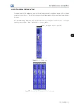
3.4 ELECTRICAL INSTALLATION
DANGER!
The following information is merely a guide for proper installation. Comply with applicable local
regulations for electrical installations.
DANGER!
Make sure the AC power supply is disconnected before starting the installation.
ATTENTION!
The CFW-11M RB can be connected in circuits with symmetrical short circuit capability up to
150000 Arms (480 V/690 V maximum).
ATTENTION!
Integral solid state short circuit protection does not provide branch circuit protection. Branch circuit
protection must be provided in accordance with applicable local standards.
3.4.1 Pre-charge Circuit
The resistors of the pre-charge circuit must be sized according to the following criteria:
- Maximum voltage.
- Maximum energy.
- Power overload capacity of the resistors during the pre-charge period (energy dissipation capacity).
The characteristics of the resistors must be obtained with their manufacturer.
Содержание CFW-11M RB
Страница 9: ...1 4 CFW 11M RB 1 Safety Instructions...
Страница 21: ...2 2 12 CFW 11M RB General Instructions...
Страница 87: ...7 7 2 CFW 11M RB Accessories...


