3
3-20 | CFW-11M RB
Installation and Connection
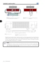
The input connections at the internal reactance are done by means of six M12 x 30 bolts (tightening torque:
60 Nm), 2 bolts per phase. The bus bars are of 40 x 10 mm (1.57 x 0.39 in) and the fastening is done
through M12 nuts inserted into the bar. Refer to the figure 3.27.
Note:
dimensions in mm (in).
22,5 OLHA
PARA IÇAMENTO
95
95
87,4
40
55,2
20
40
BARRA DE SAÍDA "U"
BARRA DE SAÍDA "V"
BARRA DE SAÍDA "W"
Ø22.5 (0.9)
hoisting hole
Input bar "S"
Input bar "T"
Input bar "R"
95
(3
.7
)
20 (0.8)
95
(3
.7
)
55
.2
(2
.2
)
40 (1.
6)
87.4 (3.4)
40 (1.6)
Figure 3.27 -
UP11 input bus bars: input connections
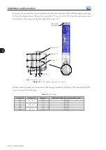
Use two cables in parallel with the recommended gauge indicated in the table 3.7 for connecting the UP11
input reactor to the input busbar.
Table 3.8 -
Input cables
Current (A)
Voltage (V)
Regimen
Minimum Cable Cross-Section Area (mm
2
)
600
380 / 480
ND
(2X) 240
515
HD
(2X) 185
470
500 / 600
ND
(2x) 150
418
HD
(2X) 120
427
660 / 690
ND
(2X) 120
340
HD
(2X) 70
Содержание CFW-11M RB
Страница 9: ...1 4 CFW 11M RB 1 Safety Instructions...
Страница 21: ...2 2 12 CFW 11M RB General Instructions...
Страница 87: ...7 7 2 CFW 11M RB Accessories...


