3
3-18 | CFW-11M RB
Installation and Connection
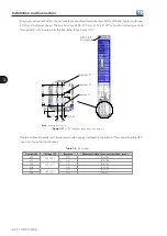
The figure 3.24 presents the adequate installation layout for three Power Units.
Inverter
-UD
+UD
T
S
R
GND
(PE)
Filter
Figure 3.24 -
Example of adequate installation layout for 3 UP11
NOTE!
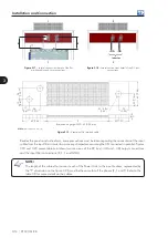
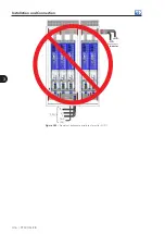
The connection of the motor cables from the filter at points different from the presented in the figure
3.24 (the figure 3.25 presents an inadequate connection form) does not assure the impedance balance
between the UPs connected in parallel, being able to cause current imbalance among the UPs.
Содержание CFW-11M RB
Страница 9: ...1 4 CFW 11M RB 1 Safety Instructions...
Страница 21: ...2 2 12 CFW 11M RB General Instructions...
Страница 87: ...7 7 2 CFW 11M RB Accessories...


