3
3-12 | CFW-11M RB
Installation and Connection
External 24 Vdc*
power supply
Pre-charge
relay
no
nc
gnd
_
24
+24
c
+24 Vdc
DI's output
Without use
Filter
M
ain
s p
ow
er
su
pp
ly
(*) Tol/- 10 %
Current: 4 A
Figure 3.15 -
General diagram
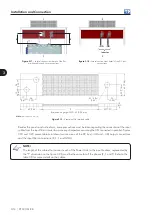
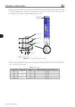
The electrical power connections of the panel must assure equal impedance at the DC bus and input
connections. Refer to the example in the figure 3.16 and to the lateral section views in figures 3.17, 3.18 and
3.20. At the output (DC Bus) and the filter input busbars, the dimensions identified as A,B,C and D must
be approximately equal to the dimensions A’, B',C' and D', respectively, as exemplified in the figure 3.16.
Содержание CFW-11M RB
Страница 9: ...1 4 CFW 11M RB 1 Safety Instructions...
Страница 21: ...2 2 12 CFW 11M RB General Instructions...
Страница 87: ...7 7 2 CFW 11M RB Accessories...


