6
6-2 | CFW-11M RB
Troubleshooting and Maintenance
6.2 FAULTS, ALARMS, AND POSSIBLE CAUSES
Table 6.1 -
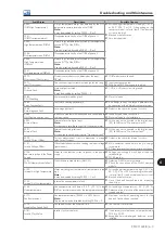
Faults, alarms and possible causes
Fault/Alarm
Description
Possible Causes
F006:
Imbalance or
Input Phase Loss
Phase missing in the input power supply or wrong
phase sequency.
;
CSR11 board connections.
;
Synchronism transformer connections.
;
Power supply connections.
F021:
DC Bus Undervoltage
DC bus undervoltage condition occurred.
;
The input voltage is too low and the DC bus
voltage dropped below the minimum permitted
value (monitor the value at Parameter P0004):
Ud < 223 V - For a 200 / 240 V input voltage
(P0296 = 0).
Ud < 385 V - For a 380 V input voltage
(P0296 = 1).
Ud < 405 V - For a 400 / 415 V input voltage
(P0296 = 2).
Ud < 446 V - For a 440 / 460 V input voltage
(P0296 = 3).
Ud < 487 V - For a 480 V input voltage
(P0296 = 4).
Ud < 530 V - For a 500 / 525 V input voltage
(P0296 = 5).
Ud < 580 V - For a 550 / 575 V input voltage
(P0296 = 6).
Ud < 605 V - For a 600 V input voltage
(P0296 = 7).
Ud < 696 V - For a 660 / 690 V input voltage
(P0296 = 8).
;
Phase loss in the input power supply.
;
Pre-charge circuit failure.
;
Parameter P0296 was set to a value above of
the power supply rated voltage.
F022:
DC Bus Overvoltage
DC bus overvoltage condition occurred.
;
The input voltage is too high and the DC bus
voltage surpassed the maximum permitted
value:
Ud > 400 V - For 220 / 230 V input models
(P0296 = 0).
Ud > 800 V - For 380 / 480 V input models
(P0296 = 1, 2, 3 or 4).
Ud > 1000 V - For 500 / 600 V input models
(P0296 = 5, 6 or 7).
Ud > 1200 V - For 660 / 690 V input models
(P0296 = 8).
;
Inertia of the driven-load is too high or
deceleration time is too short.
;
Wrong settings for parameters P0151, or P0153,
or P0185.
F030
(*)
:
Power Module U Fault
Desaturation of IGBT occured in Power Module U.
;
Short-circuit between motor phases U and V or
U and W.
(1)
F034
(*)
:
Power Module V Fault
Desaturation of IGBT occured in Power Module V.
;
Short-circuit between motor phases V and U or
V and W.
(1)
F038
(*)
:
Power Module W Fault
Desaturation of IGBT occured in Power Module W.
;
Short-circuit between motor phases W and U
or W and V.
(1)
A047:
IGBT Overload Alarm
A IGBT overload alarm occurred.
Note:
It may be disabled by setting P0350 = 0 or 2.
;
Converter input current is too high.
F048:
IGBT Overload Fault
A IGBT overload fault occurred.
;
Converter input current is too high.
(*)
For the Modular Drive it is not indicated in the HMI in which book happened the fault. For such, it is necessary to check the LED's at the
IPS1 board (refer to note
(1)
).
Содержание CFW-11M RB
Страница 9: ...1 4 CFW 11M RB 1 Safety Instructions...
Страница 21: ...2 2 12 CFW 11M RB General Instructions...
Страница 87: ...7 7 2 CFW 11M RB Accessories...


