3
CFW-11M RB |3-11
Installation and Connection
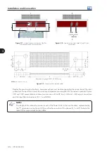
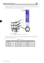
Figure 3.14 -
DC link fuses
NOTE!
In order to increase the protection, it is possible to use fuses sized to protect and withstand the AC
current of each regenerative converter power unit. Table 3.4 presents the values used by WEG.
Table 3.7 -
Rated current of the fuses according to the CFW-11M RB model
Rated Voltage
ND Current
Fuse
380 / 480 V
600 A
900 A
500 / 600 V
470 A
700 A
660 / 690 V
427 A
700 A
Fuse examples:
- 400 V line: 6.9URD33TTF0900 (FERRAZ)
- Other lines: 6.9URD33TTF0700 (FERRAZ)
3.4.4 General Connection Diagram and Layout
Figure 3.15 presents a general diagram for a converter with five power units (UP11) composed by:
;
Connections between Control Unit UC11 and the UPs (DB25 XC40 connectors and optical fibers).
;
Power connections of the UPs (+UD, -UD, R, S and T, GND).
;
Auxiliary power supply connections of the fans (220 V) and the UC11 (24 Vdc).
For a reduced number of UP11’s, connect them in crescent order (A, B, C, etc.), leaving the last positions
without connections.
Содержание CFW-11M RB
Страница 9: ...1 4 CFW 11M RB 1 Safety Instructions...
Страница 21: ...2 2 12 CFW 11M RB General Instructions...
Страница 87: ...7 7 2 CFW 11M RB Accessories...


