3
3-24 | CFW-11M RB
Installation and Connection
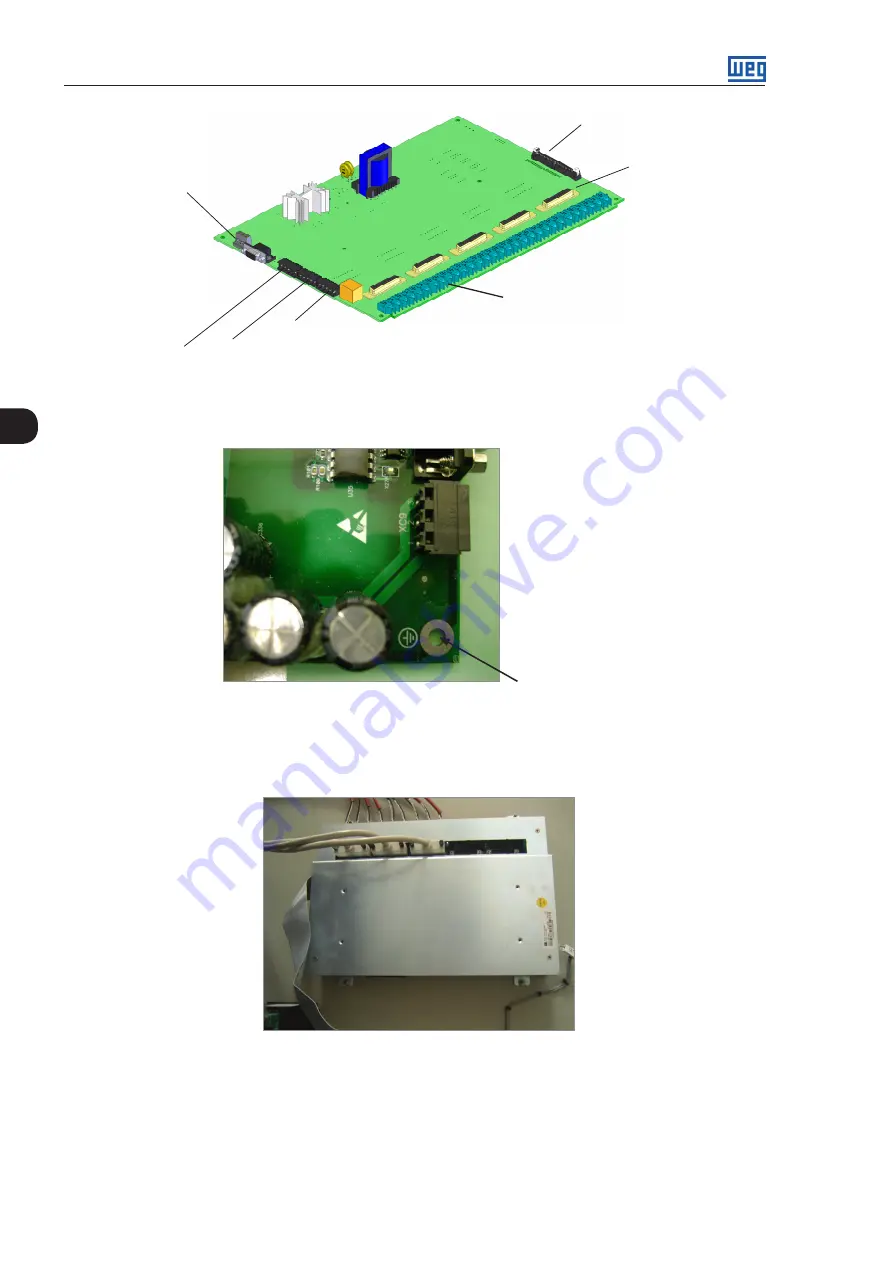
XC60: connection with
the control rack
DB25 connector
XC40A to XC40E
(connection with
the UP11)
Optical fibers connectors
(UP11 connection)
Pre-charge R
L
(XC3: 1/2/3)
DIM1 (XC1: 4/5) DIM2 (XC2: 4/5)
XC9 connector: 1,3
+24 Vdc power supply
Figure 3.32 -
IPS1 connection points
The IPS1 board mechanical installation itself makes its ground connection. This is done in several points.
Grounding point
Figure 3.33 -
IPS1 board grounding
The IPS1 shield securing screws must assure the electric contact between the shield and the panel for
grounding purposes.
Figure 3.34 -
IPS1 shield fixed on the panel
The control rack grounding must be done with a flat type braided ground strap with a minimum width
of 5 mm (0.19 in) and a minimum cross section of 3 mm
2
, with standard 6.35 mm (0.24 in) FASTON
terminal (e.g., TYCO 735075-0 and 180363-2) and M4 ring terminal. Refer to the figure 3.35.
Содержание CFW-11M RB
Страница 9: ...1 4 CFW 11M RB 1 Safety Instructions...
Страница 21: ...2 2 12 CFW 11M RB General Instructions...
Страница 87: ...7 7 2 CFW 11M RB Accessories...


