


42
INSTALLATION AND CONNECTION
This chapter describes the procedures for the electrical and mechanical
installation of the CFW-09.
These guidelines must be followed for proper CFW-09 operation.
The location of the CFW-09 installation is an important factor to assure
good performance and high product reliability.
For proper installation of the inverter, we make the following
recommendations:
Avoid direct exposure to sunlight, rain, high moisture and sea air..
Avoid exposure to gases or explosive or corrosive liquids.
Avoid exposure to excessive vibration, dust, oil or any (conductive
particles or materials).
Allowed environmental conditions:
Temperature: 0 ºC to 40 ºC (32 ºF to 104 ºF) - nominal conditions.
From 40 ºC to 55 ºC (104 ºF to 131 ºF) - with 2 % current derating for
each 1 ºC (33.8 ºF) degree above 40 ºC (104 ºF).
Relative Air Humidity: 5 % to 90 %, non-condensing.
Maximum Altitude: 1000 m (3.300 ft) – nominal conditions.
From 1000 m to 4000 m (3.300 ft to 13.200 ft) – with 1 % current
reduction for each 100 m (330 ft) above 1000 m (3.300 ft).
Pollution Degree: 2 (according to EN50178 and UL508C) (It is not
allowed the presence of water, condensation or conductive dust/
particles in the air).
3.1
MECHANICAL
INSTALLATION
3.1.1 Environment Conditions
CHAPTER
3
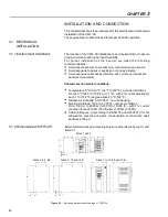
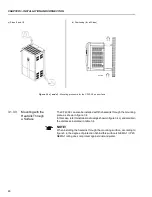
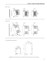
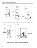
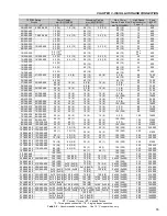
3.1.2 Dimensional of CFW-09
External dimensions and mounting holes are according to figure 3.1 and
table 3.1.
Sizes 3 to 10, 8E and 10E
A
L
P
B
D
C
H
A
A
A
L
P
C
D
C
D
B
B
H
Sizes 1 and 2
Sizes 9, 10 and 10E
Sizes 3 to 8, 8E
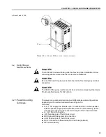
Figure 3.1
- Mounting dimensional drawings of CFW-09


