


121
CHAPTER 6 - DETAILED PARAMETER DESCRIPTION
Range
[Factory Setting]
Parameter
Unit
Description / Notes
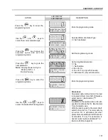
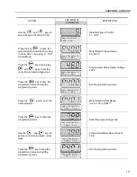
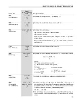
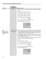
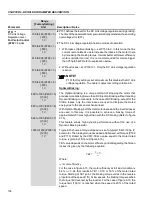
Indicates the numbers of the last, second, third and fourth previous Faults.
Fault Sequence:
Exy
P014
P015
P016
P017
P060
P061
P062
P063
P064
P065.
Ex: When the display shows 0 (zero), this means E00, 1 (one) means
E01 and so on.
P014
0 to 71
Last Fault
[ - ]
-
P015
0 to 71
Second Previous Fault
[ - ]
-
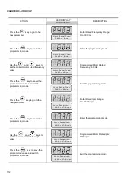
P016
0 to 71
Third Previous Fault
[ - ]
-
P017
0 to 71
Fourth Previous Fault
[ - ]
-
P018
-100 to +100
Analog Input AI1' Value
[ - ]
0.1 %
P019
-100 to +100
Analog Input AI2' Value
[ - ]
0.1 %
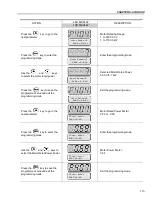
P020
-100 to +100
Analog Input AI3' Value
[ - ]
0.1 %
P021
-100 to +100
Analog Input AI4' Value
[ - ]
0.1 %
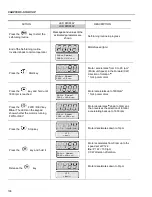
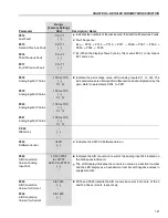
Indicate the percentage value of the analog inputs AI1 to AI4. The
indicated values are obtained after offset action and multiplication by the
gain. Refer to parameters P234 to P247.
P022
-
WEG Use
[ - ]
-
P023
V4.0X
Software Version
[ - ]
-
Indicates the CFW-09 Software Version.
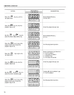
P024
LCD: -32768
A/D Conversion
to +32767
Value of Analog
LED: 0 to FFFFH
Input AI4
[ - ]
-
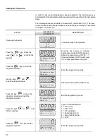
Indicates the A/D conversion result of the analog input A14 located on
the I/O Expansion Board.
The LCD display indicates the conversion value as a decimal number
and the LED display as a hexadecimal number with negative values in
supplement of 2.
P025
0 to 1023
A/D Conversion
[ - ]
Value of Iv Current
-
P026
0 to 1023
A/D Conversion
[ - ]
Value of Iw Current
-
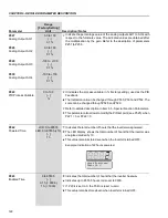
P025 and P026 indicate the A/D conversion result, in module, of the V
and W phase currents, respectively.


