


203
CHAPTER 6 - DETAILED PARAMETER DESCRIPTION
Range
[Factory Setting]
Parameter
Unit
Description / Notes
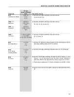
356 V to 564 V
(P296 = 3)
[534 V]
1 V
388 V to 615 V
(P296 = 4)
[583 V]
1 V
425 V to 674 V
(P296 = 5)
[638 V]
1 V
466 V to 737 V
(P296 = 6)
[699 V]
1 V
486 V to 770 V
(P296 = 7)
[729 V]
1 V
559 V to 885 V
(P296 = 8)
[838 V]
1 V
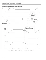
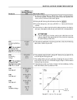
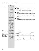
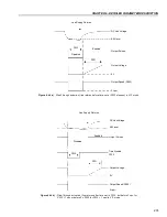
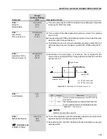
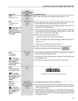
t0 - Line Loss;
t1 - Line Loss Detection;
t2 - Trip by Undervoltage (E02 without Ride-Through);
t3 - Line Recover;
t4 - Line Recover Detection;
t5 - Trip by Undervoltage (E02 with Ride-Through).
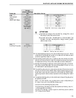
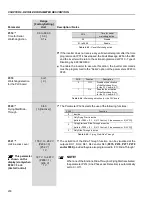
P325
0.0 to 63.9
Ride-Through
[22.8]
Proportional Gain
0.1
Regulator RT
This parameter
is shown on the
display(s) only when
P202 = 3 or 4
(Vector Control)
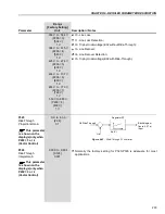
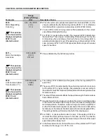
Ud Ride-Through
Kp, Ki
Blockdiagram
figure 6.27 a)
Input
Figure 6.43
- Ride-Through PI controller
Ud
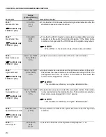
P326
0.000 to 9.999
Ride-Through
[0.128]
Integral Gain
0.001
Normally the factory setting for P325/P326 is adequate for most
applications.
This parameter
is shown on the
display(s) only when
P202 = 3 or 4
(Vector Control)


