


268
CHAPTER 8 - CFW-09 OPTIONS AND ACCESSORIES
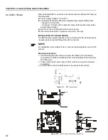
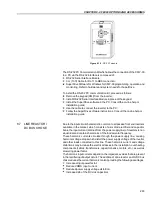
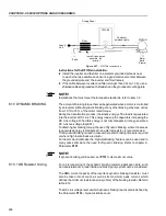
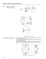
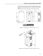
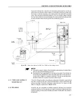
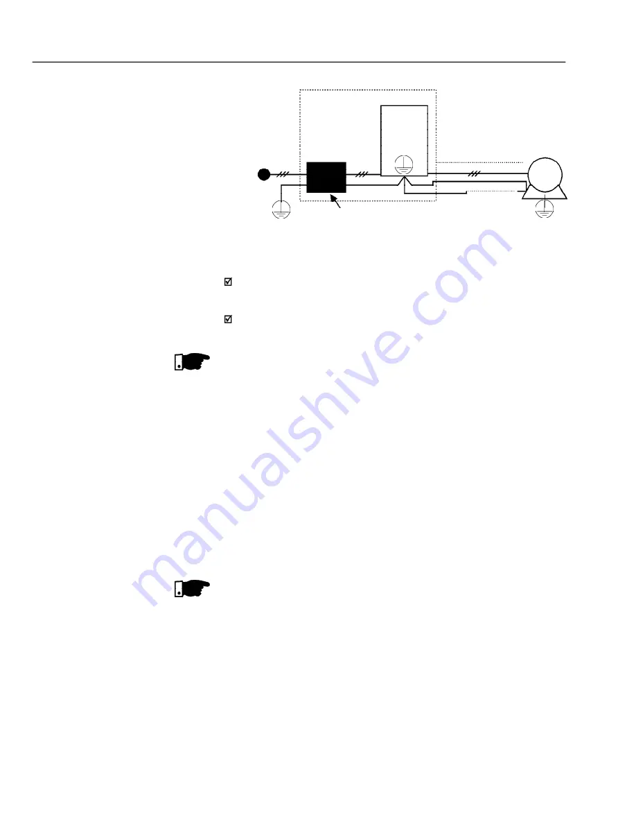
Instructions for the RFI filter installation:
Install the inverter and the filter on a metallic grounded plate as near
to each other as possible and ensure a good electrical contact between
the grounded plate and the inverter and filter frames;
If the cable between inverter and filter is longer than 30 cm (12 in), use a
shielded cable and ground each shield end on the grounded mounting plate.
NOTE!
Installations that must meet the European standards, refer to item 3.3.
The amount of braking torque that can be generated when a motor is controlled
by an inverter, without dynamic braking or any other braking schemes, varies
from 10 % to 35 % of the motor rated torque.
During the deceleration process, the kinetic energy of the load is regenerated
into the inverter’s DC Link. This energy loads up the capacitors increasing the
DC Link voltage. When this energy is not fully dissipated, it may generate a
DC Link overvoltage trip (E01).
To obtain higher braking torque, the use of Dynamic Braking, where the excess
regenerated energy is dissipated in an external resistor, is recommended.
The Dynamic Braking is used in cases where short braking times are required
or where high inertia loads are driven.
For Vector Control Modes the “Optimal Braking” feature can be used and in
many cases eliminate the need for Dynamic Braking. Refer to chapter 6,
Parameter
P151
.
NOTE!
If dynamic braking will be used, set
P151
to its maximum value.
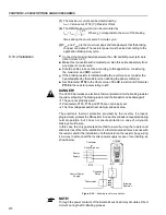
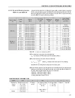
For a precise sizing of the dynamic braking resistor, application data, such
as: deceleration time, load inertia and braking duty cycle must be considered.
The RMS current capacity of the inverter’s dynamic braking transistor must
also be taken into account, as well as its maximum peak current, which
defines the minimum resistance value (ohms) of the braking resistor. Refer to
table 8.12.
The DC Link voltage level at which dynamic braking is activated is defined by
the Parameter
P153
– Dynamic Brake Level.
8.10 DYNAMIC BRAKING
8.10.1 DB Resistor Sizing
Earth
Driving Panel
Filter
CFW-09
Supply
Line
install it as near as
possible the
inverter
Motor
Earth
(Frame)
MOTOR
Conduit or
shielded cable
PE
Figure 8.21
– RFI filter connection
PE


