


164
CHAPTER 6 - DETAILED PARAMETER DESCRIPTION
Range
[Factory Setting]
Parameter
Unit
Description / Notes
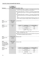
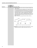
P134
Reference
Figure 6.28 a) and b)
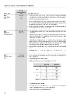
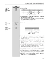
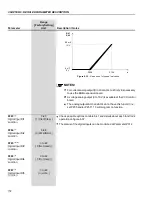
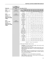
- Actuation of the analog inputs
P133
Alx Signal
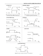
0
0 ..................................... 10 V
0 ................................... 20 mA
4 mA .............................. 20 mA
10 V .................................. 0
20 mA ................................ 0
20 mA ............................. 4 mA
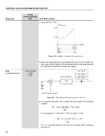
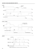
b) Active Dead Zone P233 = 1
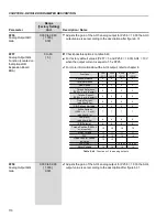
When the Analog Input AI4 is programmed for -10 V to +10 V (P246 = 4),
the curves shown in figure 6.27 are still valid, with the difference that with
AI4 negative the direction of rotation is reversed.
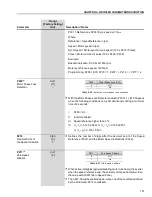
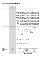
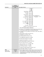
P234
0.000 to 9.999
Analog InputAI1 Gain
[ 1.000 ]
0.001
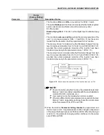
The internal values AI1', AI3', and AI4' are the results of the following
equation:
AIx' = (AIx + OFFSET x 10 V) x Gain
100
For example: AI1 = 5 V, Offset = -70 % and Gain = 1.00:
AI1' = (5 + (-70) x 10 V) x 1 = -2 V
100
AI1' = -2 V, means that the motor will run in reverse with a reference
equal to 2 V.
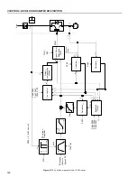
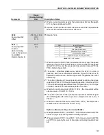
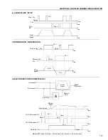
GAIN
P235
P243
P246
AIx
Figure 6.29
- Block diagram of the analog input AI1, AI3, AI4
AI1' - P018
AI3' - P020
AI4' - P021
P234, P242, P245
+
+
OFFSET (P236, 244, P247)


